
User Guide & Service Guide

USER GUIDE
Troubleshooting - Extended 3
u-line.com
SAFETY • INSTALLATION & INTEGRATION • OPERATING INSTRUCTIONS • MAINTENANCE • SERVICE
MAIN CONTROL
The main control board is very robust and is rarely the
cause of system issues. It is important to fully diagnose
the board for any suspected failures before attempting to
remove the board for replacement or service. Follow the
guidelines below to fully test and diagnose the main
control.
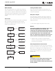
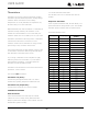
Power Fault
If the unit does not (or seems to not) power on, follow the
flow chart below to help diagnose the issue. Before
beginning it is important to first verify the unit is not
simply set to sabbath mode.
Testing The Main Control
If the main control is suspected of being faulty, the
following procedure should be performed to verify main
control for functionality.
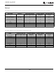
Relay & DC Outputs
One of the primary functions of the main control is to
operate the multiple relay and DC outputs during each
cycle. Verify proper operation of these relays using the
following procedure.
1. Enter “Relay Toggle” through the service menu.
NOTICE
Frequently toggling the compressor relay could
force the compressor into overload. The
compressor will automatically deactivate during
an overload and will remain deactivated until the
overload switch cools. This could take some
time. It is important to allow the compressor at
least 5 minutes off time between relay cycles.
2. Toggle the relay. Its related component should
activate / deactivate with the switching of the relay. If
it does not, test component.
Other Suspected Main Control Faults
If other components have been ruled out as being faulty
but the unit continues to have operating issues, it is most
likely due to a configuration error. Configuration errors
can be cleared by restoring the unit to its factory default
setting. Factory defaults may be restored through the
service menu.
CAUTION
!
Precautions must be taken while working with
live electrical equipment. Be sure to follow
proper safety procedures while performing tests
on live systems.
Check Voltage
At Wall Outlet
Verify Voltage At
Main Control
Voltage Input
Check Fuse F1
For Continuity
Replace
Reed Switch
Replace Main
Board
Replace
Fuse
Replace
Power Cord
Alert Customer
Of Power Failure
Is the Reed
Switch Operating
Properly?
Inspect
Customer UI
and Data Cable
Connect Test Display
Cycle Power And Check
For Operation
No Voltage
No Voltage
Voltage
Continuity
Operating
Not Operating
No Continuity
No
Yes
Voltage
41