USER GUIDE SAFETY • INSTALLATION & INTEGRATION • OPERATING INSTRUCTIONS • MAINTENANCE • SERVICE RIGHT PRODUCT. RIGHT PLACE. RIGHT TEMPERATURE. SINCE 1962.
USER GUIDE u-line.
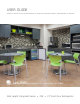
USER GUIDE u-line.com WELCOME TO U-LINE Congratulations on your U-Line purchase. Your product comes from a company with over five decades and three generations of premium modular ice making, refrigeration, and wine preservation experience. U-Line continues to be the American leader, delivering versatility and flexibility for multiple applications including residential, light commercial, outdoor and marine use.
USER GUIDE u-line.com SAFETY • INSTALLATION & INTEGRATION • OPERATING INSTRUCTIONS • MAINTENANCE • SERVICE Safety and Warning ! DANGER NOTICE This unit contains R600a (Isobutane) which is a Please read all instructions before installing, flammable hydrocarbon. It is safe for regular operating, or servicing the appliance. use. Do not use sharp objects to expedite defrosting.
USER GUIDE u-line.com SAFETY • INSTALLATION & INTEGRATION • OPERATING INSTRUCTIONS • MAINTENANCE • SERVICE Disposal and Recycling ! DANGER RISK OF CHILD ENTRAPMENT. Before you throw away your old refrigerator or freezer, take off the doors and leave shelves in place so children may not easily climb inside.
USER GUIDE u-line.com SAFETY • INSTALLATION & INTEGRATION • OPERATING INSTRUCTIONS • MAINTENANCE • SERVICE Environmental Requirements This unit is designed to operate between 50°F (10°C) and 100°F (37°C). High ambient temperatures (100°F [37°C] or higher) may reduce the unit’s ability to reach low temperatures. For best performance, keep the unit out of direct sunlight and away from heat generating equipment.
USER GUIDE u-line.com SAFETY • INSTALLATION & INTEGRATION • OPERATING INSTRUCTIONS • MAINTENANCE • SERVICE Electrical ! WARNING SHOCK HAZARD — Electrical Grounding Required. Never attempt to repair or perform maintenance on the unit until the electricity has been disconnected. Never remove the round grounding prong from the plug and never use a two-prong grounding adapter.
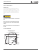
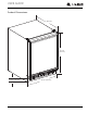
USER GUIDE u-line.com SAFETY • INSTALLATION & INTEGRATION • OPERATING INSTRUCTIONS • MAINTENANCE • SERVICE Cutout Dimensions PREPARE SITE Your U-Line product has been designed for either freestanding or built-in installation. When built-in, your unit does not require additional air space for top, sides or rear. However, the front grille must NOT be obstructed and clearance is required for an electrical connection in the rear. ! CAUTION Unit can NOT be installed behind a closed cabinet door.
USER GUIDE u-line.
USER GUIDE u-line.com SAFETY • INSTALLATION & INTEGRATION • OPERATING INSTRUCTIONS • MAINTENANCE • SERVICE Side-by-Side Installation Two units may be installed side-by-side. Cutout width for a side-by-side installation is the cutout dimension of a single unit times two. No trim kit is required. However, 1/4" (6 mm) of space 3. Place bracket over holes and attach to unit with two screws removed in step 2 using a T-25 Torx driver. Tighten screws fully. 4. Gently push units into position.
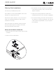
USER GUIDE u-line.com SAFETY • INSTALLATION & INTEGRATION • OPERATING INSTRUCTIONS • MAINTENANCE • SERVICE General Installation INSTALLATION 1. Plug in the power/electrical cord. LEVELING INFORMATION 1. Use a level to confirm 2. Gently push the unit into position. Be careful not to the unit is level. Level entangle the power cord. should be placed along top edge and side edge 1 3. Re-check the leveling, from front to back and side to as shown. side. Make any necessary adjustments.
USER GUIDE u-line.com SAFETY • INSTALLATION & INTEGRATION • OPERATING INSTRUCTIONS • MAINTENANCE • SERVICE Integrated Panel Dimensions INSERT CUSTOM 1/4'' THICK DOOR PANEL Insert Panel Preparation A custom door panel may be inserted into the door frame. Custom door panels can be flat or raised, as long as the maximum panel thickness where inserted into the door reveal (channel) is no more than 1/4" thick. For raised panels, the depth of the reveal is 1/4" on all four sides.
USER GUIDE u-line.com SAFETY • INSTALLATION & INTEGRATION • OPERATING INSTRUCTIONS • MAINTENANCE • SERVICE Integrated Panel Installation 5. Slide custom door panel insert into 1/4" (6 mm) channel in door front. This model accepts a 1/4" insert panel. INSERT PANEL INSTALLATION NOTICE Install the insert as follows: Use care not to damage magnet, located on door bottom when installing door insert. Do not set door on bottom edge when pushing insert into ! CAUTION Use care when handling the insert.
USER GUIDE u-line.com SAFETY • INSTALLATION & INTEGRATION • OPERATING INSTRUCTIONS • MAINTENANCE • SERVICE Grille - Plinth Installation REMOVING AND INSTALLING GRILLE ! WARNING Disconnect electric power to the unit before removing the grille. ! WARNING DO NOT touch the condenser fins. The condenser fins are SHARP and can be easily damaged. Removing the grille 1. Disconnect power to the unit. 2. Remove control knob (4). 3. Loosen the two screws (1). 4. Remove grille (2) and grille cap (3) from unit.
USER GUIDE u-line.com SAFETY • INSTALLATION & INTEGRATION • OPERATING INSTRUCTIONS • MAINTENANCE • SERVICE Door Swing All units have a zero clearance for the door to open 90°. U-Line recommends a minimum door clearance of 1/4" (6 mm) to accommodate the handle if the unit is installed next to a wall. 1/4" Min.
USER GUIDE u-line.com SAFETY • INSTALLATION & INTEGRATION • OPERATING INSTRUCTIONS • MAINTENANCE • SERVICE Door Adjustments CHECKING DOOR ALIGNMENT The unit’s door is aligned at the factory before shipment. However, its alignment could have been disturbed during shipment. NOTICE To reverse the door mounting, perform the following: 1. Remove grille (see GRILLE-PLINTH INSTALLATION). 2. Remove top hinge from cabinet (three screws). Hold door to keep it from falling.
USER GUIDE u-line.com SAFETY • INSTALLATION & INTEGRATION • OPERATING INSTRUCTIONS • MAINTENANCE • SERVICE 6. Install hinge on opposite side at bottom of cabinet. 9. Remove plastic hole plug from door handle and Align hinge outer edge with cabinet before tightening relocate to opposite side. Lift the handle slightly and screws. press on the locking tab, then gently pry the hole plug out of the hole, being careful not scratch the top cap.
USER GUIDE u-line.com SAFETY • INSTALLATION & INTEGRATION • OPERATING INSTRUCTIONS • MAINTENANCE • SERVICE First Use All U-Line controls are preset at the factory. Initial startup requires no adjustments. NOTICE U-Line recommends allowing the unit to run overnight before loading with product. ON OFF To turn the unit on or off: Press the rocker switch located below the temperature control dial in the center of the grille. CONTROL DIAL The control dial sets a single continuous temperature.
USER GUIDE u-line.com SAFETY • INSTALLATION & INTEGRATION • OPERATING INSTRUCTIONS • MAINTENANCE • SERVICE Control Operation Up Down Not Alert Light Power Used LED CONTROL FUNCTION GUIDE FUNCTION COMMAND DISPLAY/OPTIONS ON/OFF Press and release Unit will immediately turn ON or OFF.
USER GUIDE u-line.com SAFETY • INSTALLATION & INTEGRATION • OPERATING INSTRUCTIONS • MAINTENANCE • SERVICE Airflow and Product Loading NOTICE The unit requires proper airflow to perform at its highest efficiency. Do not block the front grille, or the unit will not perform as expected. Do not install the unit behind a door. When loading your unit, leave space between the evaporator and product loaded. Anything in direct contact with the evaporator is subject to freezing.
USER GUIDE u-line.com SAFETY • INSTALLATION & INTEGRATION • OPERATING INSTRUCTIONS • MAINTENANCE • SERVICE Interior Shelves REMOVING AND INSTALLING INTERIOR SHELVES For models equipped with glass shelves having shelf supports, remove the shelves as follows: 1. Open door completely. 2. Grasp the shelf edge in the center and slide the shelf from the unit. Insert the shelves as follows: 1.
USER GUIDE u-line.com SAFETY • INSTALLATION & INTEGRATION • OPERATING INSTRUCTIONS • MAINTENANCE • SERVICE Door Shelves REMOVING AND INSTALLING DOOR SHELVES 1 2 To remove the door shelf: 1. Grasp shelf in center, and lift until the shelf notches (1) clear the pins (2). 2. Carefully pull the shelf away from the door. To install the door shelf: 1. Holding the shelf in the center, center the shelf in the door at the desired location, slightly above the pins (2). 2. Lower the shelf onto the pins (2).
USER GUIDE u-line.com SAFETY • INSTALLATION & INTEGRATION • OPERATING INSTRUCTIONS • MAINTENANCE • SERVICE Cleaning If any surface discoloring or rusting appears, clean it EXTERIOR CLEANING and a nonabrasive cloth. Always clean with the grain. Vinyl Clad (Black or White) Always finish with Claire® Stainless Steel Polish and Clean surfaces with a mild detergent and warm water solution. Do not use solvent-based or abrasive cleaners.
USER GUIDE u-line.com SAFETY • INSTALLATION & INTEGRATION • OPERATING INSTRUCTIONS • MAINTENANCE • SERVICE High ambient temperature and excessive humidity can also produce frost. ! CAUTION DO NOT use an ice pick or other sharp instrument to help speed up defrosting. These instruments can puncture the inner lining or damage the cooling unit. DO NOT use any type of heater to defrost. Using a heater to speed up defrosting can cause personal injury and damage to the inner lining.
USER GUIDE u-line.com SAFETY • INSTALLATION & INTEGRATION • OPERATING INSTRUCTIONS • MAINTENANCE • SERVICE Cleaning Condenser INTERVAL - EVERY SIX MONTHS To maintain operational efficiency, keep the front grille free of dust and lint, and clean the condenser when necessary. Depending on environmental conditions, more or less frequent cleaning may be necessary. ! WARNING Disconnect electric power to the unit before cleaning the condenser. ! WARNING DO NOT touch the condenser fins.
USER GUIDE u-line.com SAFETY • INSTALLATION & INTEGRATION • OPERATING INSTRUCTIONS • MAINTENANCE • SERVICE Extended Non-Use 5. During periods of non-use, the cabinet must remain open to prevent formation of mold and mildew. Open STORAGE, VACATION AND MOVING door a minimum of 2 in. (5 cm) to provide the If not using the unit for an extended period, or otherwise necessary ventilation. stored, follow these steps completely: ! WARNING Electrical Shock Hazard. Disconnect power before servicing.
USER GUIDE u-line.com SAFETY • INSTALLATION & INTEGRATION • OPERATING INSTRUCTIONS • MAINTENANCE • SERVICE Troubleshooting • Evaporator: Refrigerant flowing through an evaporator may sound like boiling liquid. BEFORE CALLING FOR SERVICE If you think your U-Line product is malfunctioning, read the CONTROL OPERATION section to clearly understand the function of the control.
USER GUIDE u-line.com SAFETY • INSTALLATION & INTEGRATION • OPERATING INSTRUCTIONS • MAINTENANCE • SERVICE Problem Possible Cause and Remedy Product Is Not Cold Enough. Air temperature does not indicate product temperature. See CHECKING PRODUCT TEMPERATURE below. Adjust the temperate to a cooler set point. Ensure unit is not located in excessive ambient temperatures or in direct sunlight. Ensure the door is closing and sealing properly. Ensure the interior light has not remained on too long.
USER GUIDE u-line.com SAFETY • INSTALLATION & INTEGRATION • OPERATING INSTRUCTIONS • MAINTENANCE • SERVICE Warranty unit is completed and mailed back or electronically U-LINE CORPORATION LIMITED WARRANTY apply to cosmetic damages. A proof of purchase may 1. U-Line Corporation (“U-Line”) warrants each U-Line be required. submitted to U-Line.
USER GUIDE u-line.com SAFETY • INSTALLATION & INTEGRATION • OPERATING INSTRUCTIONS • MAINTENANCE • SERVICE 7. If a product defect is discovered during the applicable warranty period, you must promptly notify either U-Line at 8900 N. 55th Street, Milwaukee, Wisconsin 53223 USA or at +1.800.779.2547 or the dealer from whom you purchased the product. In no event shall such notification be received later than 30 days after the expiration of the applicable warranty period.