
User Guide
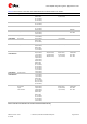
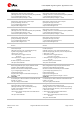
Table Of Contents
- Document information
- Contents
- 1 LARA-R2 / LARA-R6 modules description
- 2 Migration between LARA modules
- 2.1 Overview
- 2.2 Pin-out comparison between LARA modules
- 2.3 Interfaces comparison between LARA modules
- 2.3.1 VCC module supply input
- 2.3.2 V_INT 1.8 V supply output
- 2.3.3 V_BCKP RTC supply input/output
- 2.3.4 Cellular RF interfaces
- 2.3.5 System control interfaces
- 2.3.6 SIM interface
- 2.3.7 UART interfaces
- 2.3.8 USB interface
- 2.3.9 I2C interface
- 2.3.10 Digital audio interface
- 2.3.11 Clock output
- 2.3.12 GPIOs
- 2.3.13 Antenna dynamic tuning
- 2.3.14 Reserved pins
- 2.3.15 Other considerations and test points
- 2.4 Schematic for LARA modules integration
- Appendix
- A Glossary
- Related documents
- Revision history
- Contact

LARA-R2/R6 migration guide - Application note
UBX-21010015 - R02 Migration between LARA modules Page 9 of 25
C1-Public
Detailed guidelines to implement a nested application board, a comprehensive description of the
u-blox reference nested design and detailed comparisons between the u-blox SARA, LARA, LISA, and
TOBY modules are provided in the Nested design application note
[3].
2.2 Pin-out comparison between LARA modules
Table 5 shows a pin-out comparison between LARA-R2 and LARA-R6 series modules.
No
LARA-R2 series
LARA-R6 series
1
GND
GND
Ground
Ground
2
V_BCKP
RSVD
RTC supply I/O
Reserved for future use. Internally not connected.
3
GND
GND
Ground
Ground
4
V_INT
V_INT
1.8 V (typical) supply output
Generated by internal DC/DC step-down regulator,
when the module is turned on.
Test point recommended
1.8 V (typical) supply output
Generated by internal LDO linear regulator,
when the module is turned on.
Test point recommended
5
GND
GND
Ground
Ground
6
DSR
DSR
Main primary UART Data Set Ready output
(push-pull, idle high, active low)
V_INT voltage supply domain (1.8 V)
Output driver strength: 6 mA
Internal active pull-up strength: ~7.5 kΩ
Main primary UART Data Set Ready output
(push-pull, idle high, active low)
Alternative function:
Second auxiliary UART HW flow control input
(idle high, active low, with internal active pull-up enabled).
V_INT voltage supply domain (1.8 V)
Output driver strength: 2 mA
Internal active pull-up strength: ~100 kΩ
7
RI
RI
Main primary UART Ring Indicator output
(push-pull, idle high, active low)
V_INT voltage supply domain (1.8 V)
Output driver strength: 6 mA
Main primary UART Ring Indicator output
(push-pull, idle high, active low)
Alternative function:
Second auxiliary UART HW flow control output
(push-pull, idle high, active low).
V_INT level (1.8 V)
Output driver strength: 2 mA
8
DCD
DCD
Main primary UART Data Carrier Detect output
(push-pull, idle high, active low)
V_INT voltage supply domain (1.8 V)
Output driver strength: 6 mA
Main primary UART Data Carrier Detect output
(push-pull, idle high, active low)
Alternative function:
Second auxiliary UART data output
(push-pull, idle high, active low).
V_INT voltage supply domain (1.8 V)
Output driver strength: 2 mA
9
DTR
DTR
Main primary UART Data Terminal Ready input
(idle high, active low, with internal active pull-up enabled)
to be set low to activate the greeting text.
V_INT voltage supply domain (1.8 V)
Internal active pull-up strength: ~7.5 kΩ
Main primary UART Data Terminal Ready input
(idle high, active low, with internal active pull-up enabled)
to be set low to activate the greeting text.
Alternative function:
Second auxiliary UART data input
(idle high, active low, with internal active pull-up enabled).
V_INT voltage supply domain (1.8 V)
Internal active pull-up strength: ~100 kΩ