
User Guide
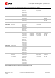
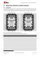
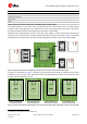
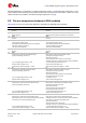
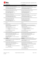
Table Of Contents
- Document information
- Contents
- 1 LARA-R2 / LARA-R6 modules description
- 2 Migration between LARA modules
- 2.1 Overview
- 2.2 Pin-out comparison between LARA modules
- 2.3 Interfaces comparison between LARA modules
- 2.3.1 VCC module supply input
- 2.3.2 V_INT 1.8 V supply output
- 2.3.3 V_BCKP RTC supply input/output
- 2.3.4 Cellular RF interfaces
- 2.3.5 System control interfaces
- 2.3.6 SIM interface
- 2.3.7 UART interfaces
- 2.3.8 USB interface
- 2.3.9 I2C interface
- 2.3.10 Digital audio interface
- 2.3.11 Clock output
- 2.3.12 GPIOs
- 2.3.13 Antenna dynamic tuning
- 2.3.14 Reserved pins
- 2.3.15 Other considerations and test points
- 2.4 Schematic for LARA modules integration
- Appendix
- A Glossary
- Related documents
- Revision history
- Contact

LARA-R2/R6 migration guide - Application note
UBX-21010015 - R02 Migration between LARA modules Page 8 of 25
C1-Public
LARA-R2 series
LARA-R6 series
USB High-Speed Interface
●
●
I2C interface
●
●
Digital Audio Interface
●
●
5
Clock output
●
●
5
GPIOs
●
●
Table 4: Summary of interfaces supported by LARA-R2/R6 migration guide modules
The LARA modules are also form-factor compatible with the u-blox SARA, LISA, and TOBY cellular
module families: although each has a different form factor, the footprints for the TOBY, LISA, LARA,
and SARA modules have been developed to ensure layout compatibility.
With the u-blox “nested design” solution, any TOBY, LISA, SARA, or LARA module can be alternatively
mounted on the same space of a single “nested” application board as described in
Figure 2, enabling
straightforward development of products supporting different cellular radio access technologies.
TOBY
SARALARA
LARA
Top View
54
22
50
656667686970
717273747576
7778
7980
8182
8384
858687888990
919293949596
11
10
8
7
5
4
2
1
21
19
18
16
15
13
12
3
20
17
14
9
6
23252628293132 242730
43
44
46
47
49
52
53
33
35
36
38
39
41
42
51
48
45
40
37
34
64636160585755 59 6256
99100
979
11
10
7
5
4
2
1
21
19
18
16
15
13
12
29
27
26
24
23
8
6
3
22
20
17
14
28
25
9
65
66
69
71
72
74
75
55
57
58
60
61
63
64
47
49
50
52
53
68
70
73
54
56
59
62
48
51
67
90
91
9278
77
76
93100
79 80 83 85 86 88 8982 84 8781
32
31
3044
45
46
145152
43 42 39 37 36 34 3340 38 3541
99 98 97 96 95 94
106 105 104 103 102 101
108 107
124 123
130 129 128 127 126 125
136 135 134 133 132 131
138 137
144 143 142 141 140 139
151 150 149 148 147 146
114 113 112 111 110 109
120 119 118 117 116 115
122 121
TOBY
Top view
64
2223252628293132
11
10
8
7
5
4
2
1
21
19
18
16
15
13
12
43
44
46
47
49
50
52
53
33
35
36
38
39
41
42
656667686970
717273747576
7778
7980
8182
8384
858687888990
919293949596
3
20
17
14
9
6
242730
51
48
45
40
37
34
63616058575554 59 6256
SARA
Top View
Figure 2: Cellular modules layout compatibility: all modules can be mounted on the same nested footprint
In details, as described in
Figure 3, a different top-side stencil (paste mask) is needed for each u-blox
module form factor (TOBY, LISA, SARA and LARA) to be alternatively mounted on the same space of
a single “nested” application board.
LISA mounting option
with LISA paste mask
ANT pad
TOBY mounting option
with TOBY paste mask
ANT pad
SARA mounting option
with SARA paste mask
ANT pad ANT pad
LARA mounting option
with LARA paste mask
LISATOBY SARA LARA
Figure 3: Top-side stencil (paste mask) designs to alternatively mount SARA, LARA, LISA, TOBY modules on the same PCB
5
LARA-R6001, LARA-R6401 and LARA-R6801 only.