
User Guide
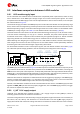
Table Of Contents
- Document information
- Contents
- 1 LARA-R2 / LARA-R6 modules description
- 2 Migration between LARA modules
- 2.1 Overview
- 2.2 Pin-out comparison between LARA modules
- 2.3 Interfaces comparison between LARA modules
- 2.3.1 VCC module supply input
- 2.3.2 V_INT 1.8 V supply output
- 2.3.3 V_BCKP RTC supply input/output
- 2.3.4 Cellular RF interfaces
- 2.3.5 System control interfaces
- 2.3.6 SIM interface
- 2.3.7 UART interfaces
- 2.3.8 USB interface
- 2.3.9 I2C interface
- 2.3.10 Digital audio interface
- 2.3.11 Clock output
- 2.3.12 GPIOs
- 2.3.13 Antenna dynamic tuning
- 2.3.14 Reserved pins
- 2.3.15 Other considerations and test points
- 2.4 Schematic for LARA modules integration
- Appendix
- A Glossary
- Related documents
- Revision history
- Contact

LARA-R2/R6 migration guide - Application note
UBX-21010015 - R02 Migration between LARA modules Page 20 of 25
C1-Public
2.3.15 Other considerations and test points
Table 6 lists the interfaces dedicated for special purposes, as the firmware update by means of u-blox
EasyFlash tool and/or for diagnostic by means of u-blox m-center tool, on LARA modules.
Module
FW update by means of u-blox EasyFlash tool
Diagnostic by means of u-blox m-center tool
LARA-R2
USB
UART (2-wire data input/output)
USB
UART (2-wire data input/output)
AUX UART (2-wire data input/output)
HSIC
LARA-R6
USB
USB
Table 6: Interfaces for FW update and/or diagnostic purposes on LARA modules
It is highly recommended to provide test points directly connected to the pins with FW update and/or
diagnostic functions available (as in particular the VUSB_DET, USB_D+ and USB_D- pins), depending
also on which interface of the module is connected to external host application processor (as the RXD
and TXD lines of the UART interface also have to be considered).
Additionally, it is recommended to provide test points directly connected to the following pins of the
modules for diagnostic purposes:
• V_INT
• PWR_ON
• RESET_N
• RSVD #33 of LARA-R6 series modules
All LARA-R2 and LARA-R6 series GND pins are intended to be externally connected to ground.
☞ For additional specific design-in guidelines, see the modules’ system integration manual [2] [5].