
User Guide
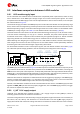
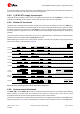
Table Of Contents
- Document information
- Contents
- 1 LARA-R2 / LARA-R6 modules description
- 2 Migration between LARA modules
- 2.1 Overview
- 2.2 Pin-out comparison between LARA modules
- 2.3 Interfaces comparison between LARA modules
- 2.3.1 VCC module supply input
- 2.3.2 V_INT 1.8 V supply output
- 2.3.3 V_BCKP RTC supply input/output
- 2.3.4 Cellular RF interfaces
- 2.3.5 System control interfaces
- 2.3.6 SIM interface
- 2.3.7 UART interfaces
- 2.3.8 USB interface
- 2.3.9 I2C interface
- 2.3.10 Digital audio interface
- 2.3.11 Clock output
- 2.3.12 GPIOs
- 2.3.13 Antenna dynamic tuning
- 2.3.14 Reserved pins
- 2.3.15 Other considerations and test points
- 2.4 Schematic for LARA modules integration
- Appendix
- A Glossary
- Related documents
- Revision history
- Contact

LARA-R2/R6 migration guide - Application note
UBX-21010015 - R02 Migration between LARA modules Page 18 of 25
C1-Public
The baud rates and configurations available and supported by LARA-R2 and LARA-R6 series modules
for the main primary UART interface may slightly differ:
• LARA-R2 series modules have the automatic baud rate and frame format detection available by
default, and they support high-speed UART data rates up to 6.5 Mbit/s.
• LARA-R6 series modules have the 115200 bit/s baud rate and the 8N1 frame format available by
default, and they support high-speed UART data rates up to 3.0 Mbit/s.
For more details about configurations of UART interfaces, see the u-blox AT commands manual
[6],
+IPR, +ICF, +IFC, &K, \Q, +UPSV, +CMUX, +USIO, +UUSBCONF AT commands, where supported).
Auxiliary UART interface
LARA-R202, LARA-R203 and LARA-R211 modules provide an auxiliary secondary 2-wire 1.8 V UART
serial interface, as alternative function of the I2C interface (SCL and SDA pins) including:
• data lines (SCL pin as AUX UART data output, SDA pin as AUX UART data input)
LARA-R6 series modules provide an auxiliary secondary 4-wire 1.8 V UART serial interface, as
alternative function of the main UART interface DTR, DSR, DCD and RI pins, including:
• data lines (DCD pin as AUX UART data output, DTR pin as AUX UART data input)
• HW flow control lines (RI as AUX UART flow control output, DSR as AUX UART flow control input)
The data lines of the auxiliary UART interfaces of LARA series modules are electrically compatible, so
that the same compatible external circuit can be used. However, the AUX UART data input and output
functions are available on different pins comparing LARA-R2 and LARA-R6 series modules. It is
recommended to use the V_INT output to supply the module side of external voltage translators
connected to the AUX UART.
The baud rates and configurations available and supported by LARA-R2 and LARA-R6 series modules
for the auxiliary UART interface may slightly differ: see the u-blox AT commands manual
[6] (+IPR,
+ICF, +IFC, &K, \Q, +USIO, +UUSBCONF AT commands, where supported).
2.3.8 USB interface
LARA-R2 and LARA-R6 series modules provide a compatible USB 2.0 High-Speed interface including:
• VUSB_DET input pin to detect the presence of an external USB host, and enable the USB interface
of the module by applying an external valid USB VBUS voltage (1.5 V minimum, 5.0 V typical),
• USB_D+ and USB_D- data and signaling lines according to the USB 2.0 standard.
The USB interface supports AT commands and data communication, GNSS tunneling, the FW update
by means of FOAT, the FW update by means of the u-blox EasyFlash tool, and the diagnostic trace
logging functions on all the LARA-R2 and LARA-R6 series modules.
It is highly recommended to provide accessible test points on VUSB_DET, USB_D+ and USB_D- pins
of LARA-R2 and LARA-R6 series modules, for FW update and diagnostic.
The configurations available and supported by LARA-R2 and LARA-R6 series modules for the USB
interface may slightly differ: see the related data sheet of the modules
[1] [4], and the u-blox AT
commands manual [6] (+USIO, +UUSBCONF AT commands, where supported).
☞ The USB interface of the LARA-R6 series modules is enabled only if an external voltage detectable
as High logic level is applied at the VUSB_DET input during the switch-on boot sequence of the
module.
2.3.9 I2C interface
LARA-R2 and LARA-R6 series modules provide a compatible 1.8 V I2C interface (SDA, SCL pins)
available to communicate with external u-blox GNSS chips / modules, and with external compatible