
User Guide
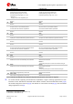
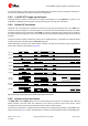
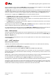
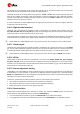
Table Of Contents
- Document information
- Contents
- 1 LARA-R2 / LARA-R6 modules description
- 2 Migration between LARA modules
- 2.1 Overview
- 2.2 Pin-out comparison between LARA modules
- 2.3 Interfaces comparison between LARA modules
- 2.3.1 VCC module supply input
- 2.3.2 V_INT 1.8 V supply output
- 2.3.3 V_BCKP RTC supply input/output
- 2.3.4 Cellular RF interfaces
- 2.3.5 System control interfaces
- 2.3.6 SIM interface
- 2.3.7 UART interfaces
- 2.3.8 USB interface
- 2.3.9 I2C interface
- 2.3.10 Digital audio interface
- 2.3.11 Clock output
- 2.3.12 GPIOs
- 2.3.13 Antenna dynamic tuning
- 2.3.14 Reserved pins
- 2.3.15 Other considerations and test points
- 2.4 Schematic for LARA modules integration
- Appendix
- A Glossary
- Related documents
- Revision history
- Contact

LARA-R2/R6 migration guide - Application note
UBX-21010015 - R02 Migration between LARA modules Page 16 of 25
C1-Public
It is recommended to sense the status of the V_INT output to define when the module is switched on,
and it is recommended to provide a test point for diagnostic.
2.3.3 V_BCKP RTC supply input/output
LARA-R2 series modules provide the RTC supply input/output at the V_BCKP pin, which is not
available on LARA-R6 series modules, having the same pin internally not connected.
2.3.4 Cellular RF interfaces
LARA-R2 and LARA-R6 series modules provide the primary RF input/output line at the ANT1 pin,
which must be connected to a suitable antenna to transmit and receive cellular RF signals, and they
provide the secondary RF input line at the ANT2 pin, which is intended to be connected to an antenna
to receive cellular RF signals in LTE and 3G radio access technologies implementing the Rx diversity
function.
The same optional antenna detection circuit can be implemented for LARA-R2 and LARA-R6 series
modules using the available optional ANT_DET input pin.
While selecting the antenna for LARA cellular modules, consider the frequency range supported by
each LARA module, as illustrated in
Figure 5.
= 3G bands
= 2G bands
= LTE bands
LEGENDA
LARA-R204
LARA-R211
LARA-R202
LARA-R203
LARA-R220
LARA-R280
LARA-R281
800 850 900 950 1700 1750 1800 1850 1900 1950 2000 2050 2100 2150 2200
1313
4 4
746 787 1710 2155
750700
800 850 900 950 1700 1750 1800 1850 1900 1950 2000
2050 2100 2150 2200
20
791
750
1710
20 3 3
960 1880
700
900900 1800 1800
800 850 900 950 1700 1750 1800 1850 1900 1950 2000
2050 2100 2150 2200
12
699 1710
750
4 42 2
700
V II IIV
894 2155
12 55
800 850 900 950 1700 1750 1800 1850 1900 1950 2000
2050 2100 2150 2200
12
699 1710
750
4 42 2
700
746 2155
12
800 850 900 950 1700 1750 1800 1850 1900 1950 2000
2050 2100 2150 2200
830 890 1920 2170
750700
800 850 900 950 1700 1750 1800 1850 1900 1950 2000 2050 2100 2150 2200
703
750
1710
3 3
960
700
88
II
2170
28 28
1119 19
800 850 900 950 1700 1750 1800 1850 1900 1950 2000 2050 2100 2150 2200
703
750
1710
3 3
960
700
88
II
2170
28 28
20 20
11
650600
650600
650600
650600
650600
650600
650600 2550 2600 2650 2700
2500 2690
7 7
2550 2600 2650 2700
2550 2600 2650 2700
2550 2600 2650 2700
2550 2600 2650 2700
2550 2600 2650 2700
2550 2600 2650 2700
2250 2300 2350 2400 2450 2500
2250 2300 2350 2400 2450 2500
2250 2300 2350 2400 2450 2500
2250 2300 2350 2400 2450 2500
2250 2300 2350 2400 2450 2500
2250 2300 2350 2400 2450 2500
2250 2300 2350 2400 2450 2500
800 850 900 950 1700 1750 1800 1850 1900 1950 2000
2050 2100 2150 2200
699 1710
750700
960 2170
650600
850
900900 1800
1900 1900
1800
850
12 12
13
28
88
28
20 20
4 42 2
3 3 11
13
55
19 19
26 26
18 18
V
VIIIVIII
II IIV
II
2550 2600 2650 2700
2300 2690
7 7
39
40 41
38
2250 2300 2350 2400 2450 2500
LARA-R6001
LARA-R6001D
800 850 900 950 1700 1750 1800 1850 1900 1950 2000
2050 2100 2150 2200
617 1710
750700
894 2200
650600
7171
12 12
13
4 42 2
66 66
13
1414
55
2550 2600 2650 27002250 2300 2350 2400 2450 2500
LARA-R6401
LARA-R6401D
800 850 900 950 1700 1750 1800 1850 1900 1950 2000
2050 2100 2150 2200
703 1710
750700
960 2170
650600
850
900900 1800
1900 1900
1800
850
2550 2600 2650 2700
2500 2690
28 28
4 42 2
3 3 11
II
7 7
2250 2300 2350 2400 2450 2500
LARA-R6801
V
VIIIVIII
II IIV
8820 20
55
19 19
26 26
18 18
Figure 5: Summary of operating frequency bands supported by LARA modules
2.3.5 System control interfaces
The PWR_ON and the RESET_N input lines have internal pull-up resistors on LARA-R2 and LARA-R6
series modules, and both lines are intended to be driven by external open drain drivers: same
compatible external circuits can be implemented for all the LARA modules.
The switch-on sequence of LARA-R2 series modules can be triggered by applying a valid VCC power
supply (see section
2.3.1), while LARA-R6 series modules remain switched off after a valid VCC power