VideoEdge IP Box Camera Installation & Operation Guide Version1.
Copyright Under copyright laws, the contents of this manual may not be copied, photocopied, reproduced, translated or reduced to any electronic medium or machine-readable form, in whole or in part, without prior written consent of Tyco International Ltd. © Copyright 2009 and its Respective Companies. All Rights Reserved, American Dynamics 6600 Congress Avenue Boca Raton, FL 33487, U.S.A.
Table Of Contents SAFETY PRECAUTIONS .............................................................................6 1. PRODUCT FEATURES.............................................................................7 1.1 PRODUCT INSTRUCTIONS .....................................................................7 1.2 PRODUCT FEATURES ...........................................................................8 1.3 TECHNICAL SPECIFICATIONS ................................................................8 2.
Installation and Operation Guide 4.5 TCP/IP CONFIGURATION SETTING ......................................................25 4.6 CONNECTION TESTING .......................................................................27 5. Operation Instructions for the Network...............................................29 5.1 MICROSOFT INTERNET EXPLORER ......................................................30 5.1.1 Connecting the IP camera ................................................................................
SAFETY PRECAUTIONS All the following safety and operational instructions to prevent harm or injury to the operator(s) or other persons should be read carefully before the unit is activated. WARNING To prevent fire or shock hazard, avoid exposing this unit to rain or moisture. Do not block ventilation openings. Do not place anything on top of the unit that might spill or fall into it.
Installation and Operation Guide 1. PRODUCT FEATURES 1.1 Product Instructions The VideoEdge IP Box Camera ADCIPEB is a user-friendly device which combines cutting-edge sophistication with practical reliability and convenience, high performance with smooth remote communication. Just plug in the network cable and you’ll get live streaming video and audio anytime, any place.
1.2 Product Features • 1/3" SONY Super HAD CCD. • Mechanical IR Cut Filter. • MPEG4 / MJPEG video compression. • High resolution: 520 TV • Embedded web server. • Supports a built-in microphone. • Supports motion detection. • Supports the SD card for alarms & scheduled recording. • Supports USB interface for basic network setup. • Supports day & night function. 1.3 Technical Specifications General: ‧Built-in Web Server and network interface. You don’t need a PC to operate.
Installation and Operation Guide ‧Image frame rate: up to 30 (25) frames/second. ‧Supports two compression modes, the Motion - JPEG and the MPEG4. ‧5 levels of compression provided. The file size of an M-JPEG compressed image depends on the image’s actual content. Images with a lot of detail will generate bigger files. The level of compression determines the image quality. High compression requires smaller files while low compression gives you finer image quality along with bigger files.
Dimensions and weight are as follows. ‧Height: 55 (mm) Dimensions / ‧Width: 95 (mm) Weight ‧Length: 62 (mm) ‧Weight: 306 g (Not including power supply and mini-tripod.) ‧CD-R x 1 Accessories Included: 10 ‧Power supply: 12V DC/2A. ‧Instruction manual.
Installation and Operation Guide 2. DESCRIPTION OF THE FRONT/REAR VIEW 2.1 Front Panel and Rear Panel -- Front Panel -- -- Rear Panel -- 2 1 3 4 6 7 5 8 1 MICROPHONE: The IP camera has an additional audio function. The device has a 2 Plug Inlet: An AC 24V or a DC 12V inlet that connects to an external power supply. microphone built into its front panel which records sound.
2.2 Flank Panel -- Left Flank Panel -- 1 2 3 4 -- Right Flank Panel -- 6 5 1. Lens Mount: This IP camera is used with either a C or a CS mount lens. 2. DIP Switch: 7 1. AES: Auto electric shutter. 2. DC IRIS: Use an auto iris (DC drive) 3. DHCP: Turn On / Turn Off to use the DHCP protocol. If the switch points upwards, the device can change the setup of network function (enable/disable) via the network. 4.
Installation and Operation Guide Alarm wiring diagram: 4. RESET: Recover to factory default. 5. 5pin MINI USB Port: The user can use a USB device cable to connect the IP camera to the USB port on the PC. 6. ALC VR: Iris control VR. When an auto iris (DC Drive) lens is used, this VR is used to adjust the iris for different lighting environments. Adjust the VR clock-wise to open the iris and counter-clockwise to close the iris of the camera. 7. IRIS: Auto iris connector.
2.3 The USB function By connecting the IP camera with a PC via the USB connector, the IP camera can provide two different functions. 1. Insert an SD card: As a card reader. Insert an SD card into the IP camera, then connect to the PC. You might transfer files between the SD card and the PC. Once you've connected your IP camera to your computer, the Windows system will detect the connection and ask you what you want to do with your SD card.
Installation and Operation Guide 2.4 Bracket mount installation The underside of the camera has a screw hole for attaching the bracket to the camera. Please follow the steps below to install the camera on the bracket. Step 1: Rotate the screw in the bracket to fix the bracket to the camera. Step 2: Fix the bracket to the ceiling. Step 3: Rotate & fix the camera angle fixer at the selected angle.
3. INSTALLATION Please follow the instructions and the diagram below to set up the system. NOTE: The IP camera is linked by its Video Out connection via a BNC connector to a monitor's Video In connection. If this connection is there, you can see some information on the monitor screen, such as the IP camera factory default Static IP address(192.168.1.168). But the IP camera Static IP address can only appear if there is a connection between the IP camera and another device.
Installation and Operation Guide 3.3 CONNECTING WITH A MULTIPLEXER LAN CAMERA 1 LAN CAMERA 2 TO LAN CAMERA VIDEO OUT BNC CONNECTOR LAN CAMERA 16 3.4 UPDATING SYSTEM SOFTWARE If the system software of the IP camera needs to be upgraded, please take the following steps to safely process it. NOTE: Before carrying out the following procedures, please ensure the SD card is working and the file of the system firmware is intact 1. Format an SD card using the FAT format. 2.
If the message "UPDATE NG RESET PLEASE" appears rather than "UPDATE OK RESET PLEASE", please write down the error messages shown on the screen and inform your technical support, while ignoring the following steps. 7. Power off the IP camera when this update process is finished, then remove the SD card from the IP camera. 8. Reconnect the Ethernet cable to the RJ-45 port as necessary. 9. Power ON the IP camera and it will work normally if the entire update procedure goes correctly. 10.
Installation and Operation Guide 3.5 IP camera SD card Troubleshooting 1. Check if the SD card position is correct or not. Please refer to the manual for the related information. 2. Correctly insert the SD card after powering the IP camera on. The "SD" icon displays in the upper-right corner of the monitor screen. If not, it means the device detection has failed. Please contact your technical support and ignore the following steps. 3. If a check mark appears, please check the following: a.
4. Network Configuration 4.1 Cable Connections Please follow the instructions below to connect your IP camera to a computer or a network and to choose a proper RJ-45 cable configuration for connections. Physical specifications of the RJ-45 cable for Ethernet Wire Type Cat. 5 Connector Type RJ-45 Max. Cable Length 100 m Hub Wiring Configuration Straight Through PC Wiring Configuration Straight 4.1.1 Connect to a computer Use a straight LAN cable to connect directly to a computer.
Installation and Operation Guide 4.1.2 Connect to a LAN Hub (INTRANET) The RJ-45 PIN configuration for connecting with a LAN Hub is shown below.
4.2 Configure Your IP Camera Network Settings Upon connecting with the network hardware, you need to activate the network function and configure the proper network settings of the IP camera. 4.2.1 Enable DHCP Function This function can only work if the LAN, which the unit is connected to, has a DHCP server. If the DHCP server is working, please move the dip switch points up to 3 on the flank panel; now the IP camera will obtain an IP address automatically from the DHCP server.
Installation and Operation Guide NOTE: When connecting to a network, each connected IP camera must be assigned a unique IP, which must be in the same class type as your network address. IP addresses are written as four sets of numbers separated by periods; for example, 192.168.1.1 Therefore, if the connected network is identified as Class C, for example, the first three sets of numbers of the IP camera IP address must be the same as the network address.
4.3 TCP/IP Communication Software Follow the procedure below to install the TCP/IP communication program in your computer. 1. Open the Start menu from your computer, and select the Settings/Control Panel option. 2. Double click the Network icon to enter the windows. 3.
Installation and Operation Guide components list. If the TCP/IP is included, please process section 4.5. If it is not included, please follow section 4.4 to install the TCP/IP. 4.4 TCP/IP Installation During the installation, you will be requested to insert the Windows CD-ROM. After installation, the PC may be restarted. 4.5 TCP/IP configuration setting 1. Click Start → Settings → Control Panel → Network.
2. Select TCP/IP, and then click Properties. NOTE: Before processing the IP camera installation in a WAN, please make sure the Internet connection works properly. If not, please contact your ISP provider. If you are using a DHCP server, please select Obtain an IP address automatically. Any assigned IP address for the connected IP cameras must be in the same class type as the server. If there is no DHCP server, please select specify an IP address and type in the IP address of your PC.
Installation and Operation Guide 4.6 Connection Testing With the previous settings, follow the instructions below to ensure whether you have established the connection successfully. 1. Click Start → Programs → MS-DOS Prompt 2. Enter ping 192.168.1.168, then enter. (See the sample screen below). ** This is the IP address of IP camera that is assigned for the connected IP camera in step2.
If you receive a response as in the sample screen below, the connection hasn’t been successfully established. Please re-check all the hardware and software installations by repeating sections 4.4 and 4.5. If you still can’t establish the connection after rechecking, please contact your dealer. Type Camera IP address If you receive a response as in the sample screen below, you have successfully made the connection.
Installation and Operation Guide 5. Operation Instructions for the Network The Microsoft Internet Explorer in a PC provides the functions of monitoring remote zones or watching recorded data through the TCP/IP protocol. The details are listed as follows. RJ-45 PIN configuration for Ethernet PIN NO. 1. 2. 3. 4. 5. 6. 7. 8. PIN Assignment TX + TX RX + Not Connected Not Connected RX Not Connected Not Connected RJ-45 socket 12345678 Physical specification for Ethernet Wire type Cat.
5.1 Microsoft Internet Explorer 5.1.1 Connecting the IP camera 1. Start up Microsoft Internet Explorer, and then follow the steps below to connect the IP camera. 2. Click on the URL block at the top of the window. 3. Enter the URL address of the IP camera into the URL block and press the “Enter” button to enter the home page. 4. Scroll to the bottom of the page, with its six icons, "Video", "Network", "System", "Application", "SD card" and "Pan/Tilt".
Installation and Operation Guide Browsing images from the IP camera The images from the IP camera are displayed on the home page when online with the IP camera. There are also additional settings provided on the home page. MJPEG mode or MPEG4 mode display different display formats on their home page. Homepage of MJPEG mode Homepage of MPEG4 mode Click on the Video button to enter the image-setting page. Click on the Network button to enter the network-setting page.
5.1.2 Change Video Setting Please follow the steps below to change the image setting through the network as necessary. 1. Click on the Video button on the home page to enter the image-setting page. Video setting page of MJPEG mode Video setting page of MPEG4 mode 2. Adjust the image setting including “Device Title”, “Resolution”, “Quality”, “Frame rate” (MPEG4 mode only), “Format”, “Viewer Type” (MJPEG mode only), and “MJPEG Deinterlace” (MJPEG mode only) as necessary. 3.
Installation and Operation Guide 5. Click on the Privacy Mask button to enter the Privacy Mask page. 6. Click on the Day & Night button to enter the Day & Night page. i. Click on the drop-down list to choose the Day & Night mode of “Auto”, “Day mode”, “Night mode” and “Schedule”. ii. Set the values of Focus Adjust and Sensitivity. iii. Click on the Submit button to submit the new Day & Night setting.
to set the period of the focus adjustment at “30 seconds”, “1 minute”, “2 minutes”, “3 minutes”, “5 minutes”, and “10 minutes”, or just select “disable” to deactivate the function. NOTE: In the “Schedule” mode, you can click the icon to set the Day or Night mode of each hour. “0” means “00:00~00:59”, “1” means “01:00~01:59”, and so on. 7. Click on the Home button to return to the home page while the new image setting acts on the images to effect the desired changes instantly.
Installation and Operation Guide Frame rate: Click on the drop-down list to choose the frame rates of “5FPS”, “10FPS”, “15FPS”, “24FPS” or “(25) 30FPS”. Format: Click to choose the “MJPEG” or the “MPEG4” mode. Fine Tune mode: White Balance: Scroll to choose the mode from “Auto”, “Fluorescent (3200K)”, “Indoor (4200K)”, “Outdoor (6500K)”, ”Push Hold”. Flickerless: Mark the “Flickerless” “ON” or “OFF”. Click your choices to enable. Mirror: Mark the “Mirror” “ON” or “OFF”.
5.1.3 Change the Network Setting Please follow the steps below to change the network setting through the network as necessary. Set the network options and IP address. 1. Click on the Network button in the home page to enter the Network page. 2. The accessible networks here are the “FTP” (for PAL only), “SMTP” (for PAL only), “SNTP”, “DDNS”, “PPPoE”, ”UPnP” and the ”Traffic”. 3. Enter the “IP Address”, “Netmask”, “Default gateway”, “Primary nameserver”, and “HTTP Port” as necessary. 4.
Installation and Operation Guide Description of function keys: IP Address: Enter the 4-byte IP Address in the appropriate blank space (the value in each box may be anywhere between 0 and 255). Every IP camera has to own an IP address to be identified on the network. Netmask: Enter the 4-byte Subnet Mask in the required blank spaces (usually any numbers between 0 and 255). It is used to identify the subnet where the IP camera is sited.
Change the Network Setting — FTP (MJPEG mode only). Please follow the steps below to change the FTP setting via the network as necessary, to upload recording data live. (*FTP function is for PAL version only.) 1. Click on the FTP button on the upper left menu to enter the “FTP Server Setting” page. 2. Enter the “FTP Server” address, the “User Name”, and the “Password” of the FTP Server; and set the “File Upload Path” of the image files when necessary. 3.
Installation and Operation Guide Change the Network Setting — SMTP (MJPEG mode only). Please follow the steps below to change the SMTP setting through the network as necessary. (*SMTP function is for PAL version only.) 1. Click on the SMTP button on the upper left menu to enter the “SMTP Server Setting” page. 2. Click “My Server Requires Authentication” to checkmark the box and activate the function. 3.
Change the Network Setting — SNTP. Please follow the steps below to change the SNTP setting through the network as necessary. 1. Click on the SNTP button on the upper left menu to enter the “SNTP Server Setting” page. 2. Enter the IP Address of the SNTP server, and choose one of the time zones as and when necessary. 3. Click “Automatically Adjust for Daylight Saving Time Changes” to checkmark the box and activate the function. 4. Click on the Submit button to submit the new SNTP setting. 5.
Installation and Operation Guide Change the Network Setting — DDNS. The “Network” page has, on its upper left, the “DDNS” icon. Please follow the steps below to change the DDNS setting through the network as necessary. 1. Click on the DDNS button on the upper left menu to enter the “DDNS Setting” page. 2. Click “Enable DDNS Function” to checkmark the box and activate the function. 3. Click ”DDNS Type” to open the list of two DDNS modes to choose from: “DynDNS” and “hn”.
Description of function keys: Enable DDNS Function: Checkmark to activate the function. DDNS Type: Click to open the list of two DDNS modes to choose from: “DynDNS” and “hn”. Click on the “Apply” button and connect this website automatically and enter it. Enter your dynamic IP Address and Email Address. If they are accepted by the website, you will get an Email containing your DDNS Account and DDNS Password in your Email box. 42 DDNS Host Name: Enter your host name in the attached space.
Installation and Operation Guide Change the Network Setting — PPPoE. The “Network” page has, on its upper left, the “PPPoE” icon. Please follow the steps below to change the PPPoE setting through the network as necessary. 1. Click on the PPPoE button on the upper left menu to enter the “PPPoE Setting” page. 2. Click on the “PPPoE Mode” to activate the function. 3. Enter the PPPoE “Account” and the PPPoE “Password”. 4. Click on the Submit button to submit the new setting. 5.
Change the Network Setting —UPnP. The “Network” page has, on its upper left, the “UPnP” icon. Please follow the steps below to change the UPnP setting through the network as necessary. 1. Click on the UPnP button on the upper left menu to enter the “Universal Plug and Play” page. 2. Click “Enable UPnP” to checkmark the box and activate the function. 3. Enter the UPnP “Max Expired Age”, the “SSDP Port” and the “UPnP Port”. 4.
Installation and Operation Guide Change the Network Setting — IP Filter The “Network” page has, on its upper left, the “IP Filter” icon. Please follow the steps below to change the IP Filter setting through the network as necessary. 1. Click on the IP Filter button on the upper left menu to enter the “Network Setting” page. 2. Click “Enable IP Filter” to checkmark the box and activate the function. 3. Select the Default policy. 4. Set the Allow/Deny IP Filter policy and enter its IP address.
Change the Network Setting —Network Traffic. The “Network” page has, on its upper left, the “Traffic” icon. Please follow the steps below to change the UPnP setting through the network as necessary. 1. Click on the Traffic button on the upper left menu to enter the “Network Traffic” page. 2. Enter the “Maximum Upload Bandwidth” and the “Maximum Download Bandwidth”. 3. Click on the Submit button to submit the new setting. 4. Click on the Home button to return to the home page.
Installation and Operation Guide 5.1.4 Change the System Setting Please follow the steps below to change the date and time of the system setting through the network as necessary. Set the Date and Time of the system 1. Click on the System button in the home page to enter the “Date And Time” page (default). 2. Choose one of the three modes shown on the page to set the Date and Time of the system. The three modes are “Set Manually”, “Synchronize With Computer Time”, and “Synchronize With SNTP Server”. 3.
Change the System Setting — Timestamp. Please follow the steps below to change/add the timestamp through the network as necessary. 1. Click on the Timestamp button on the left side of the “System - Date and Time” page to enter the “System - Timestamp” page. 2. Click “Enable Timestamp” to checkmark the box and activate the function 3. Add or modify any timestamp’s data as necessary. 4. Enter the "Timestamp Color" you have chosen. 5. Enter the "Timestamp Location" you have chosen. 6.
Installation and Operation Guide Change the System Setting — Users. Please follow the steps below to change/add the users’ authority through the network as necessary. 1. Click on the Users button on the left side of the “Date and Time” page to enter the “Users” page. 2. Add, modify or delete any user’s data as necessary. 3. Click on the Submit button to submit the new user’s settings. 4. Click on the Home button to return to the home page.
Change the System Setting — Digital I/O. Please follow the steps below to change the Digital I/O through the network as necessary. 1. Click on the Digital I/O button on the left side of the “Date and Time” page to enter the “Digital I/O Setting” page. 2. Mark the “Digital Input” “ON” or “OFF” and the “Digital Output” “ON” or “OFF”. Click your choices to enable. 3. Click on the Submit button to submit the new user’s settings. 4. Click on the Home button to return to the home page.
Installation and Operation Guide Change the System Setting — Audio. Please follow the steps below to change the Audio setting through the network as necessary. 1. Click on the Audio button on the left side of the “Date and Time” page to enter the “Audio Setting” page. 2. Mark the “Audio” “ON” or “OFF”. 3. Click on the Submit button to submit the new user’s settings. 4. Click on the Home button to return to the home page. NOTE: This setting is for turning the audio of the Camera on/off automatically.
Change the System Setting — RS485 Setting. Click on the RS485 Setting button on the left side of the “Date and Time” page to enter the “RS485 Setting” page. Description of function keys: Baud rate: Eight different speeds can be used: 2400 baud per second, 4800 baud, 9600 baud, 19200 baud, 28800 baud, 38400 baud, 57600 baud and 115200 baud. Type: Choose one of the types. Device ID: You have the option of using an ID code (any number between 1 and 255). Raw format: Set to transmit the ASCII codes.
Installation and Operation Guide Change the System Setting — Update Firmware. Please follow the steps below to update the firmware through the network as necessary. 1. Click on the Update Firmware button on the left side of the “Date and Time” page to enter the “Update Firmware” page. 2. Click on the “Browse…” button to select the UPDATE.BIN file which was copied into your computer. 3. Click on the “Update” button. NOTE: DO NOT power off the IP camera during firmware update.
View the Event Logs. Please follow the steps below to view events through the network as necessary. 1. Click on the Events button on the upper left above to enter the “Event Log” page. 2. Choose one of the three buttons shown on the page to view an event when necessary. The three buttons are titled “First Page”, “Previous 20”, and “Next 20”. Description of function keys: 54 First Page: Displays the first page. Previous 20: Displays the previous 20 pages. Next 20: Displays the next 20 pages.
Installation and Operation Guide 5.1.5 Change the Application Setting Please follow the steps below to change the application setting through the network as necessary. Change the Application Setting — FTP Application Setting (MJPEG mode only). Please follow the steps below to change the FTP setting via the network as necessary to upload recording data live. (*FTP function is for PAL version only.) 1. Click on the Application button on the home page to enter the “FTP Application Setting” page (default).
Change the Application Setting — SD Card Application Setting. Please follow the steps below to change the SD CARD setting via the network as necessary, to upload recording data live. 1. Click on the SD card button on the top left to enter the “SD Card Application Setting” page. SD Card setting page of MJPEG mode SD Card setting page of MPEG4 mode You can choose which SD card storage format to use, MJPEG (MJPEG mode only) or AVI. 2. Click on your selected format and "Submit" to set it. 3.
Installation and Operation Guide Change the Application Setting —SMTP Application Setting (MJPEG mode only). Please follow the steps below to change the SMTP setting via the network as necessary. (*SMTP function is for PAL version only.) 1. Click on the SMTP button on the left side to enter the “SMTP Application Setting” page. 2. Enter the attached file number as and when necessary. The maximum number which can be used is 8. 3.
Change the Application Setting —Language Setting. Please follow the steps below to change the Language setting via the network as necessary. 1. Click on the Language button on the left side to enter the “Language Setting” page. You have an option as to which language to use. The default is “English” 2. 58 Choose your selected language and click "Submit" to set it.
Installation and Operation Guide Change the Application Setting —Record Application Enable Setting. Please follow the steps below to change the setting via the network as necessary. 1. Click on the Enable Record button on the left side of the record to enter the “Record Application Enable Setting” page. Record setting page of MJPEG mode 2. Record setting page of MPEG4 mode Click “Enable Record – UPLOAD Via FTP” to checkmark the box and activate the function (*FTP function is for PAL version only). 3.
Change the Application Setting —Record - Schedule. 1. Click on the Application button on the home page to enter the “Record - Schedule” page. 2. Check/uncheck any/all of the first seven boxes set vertically in the upper half of the “Schedule” page to enable/disable the programmed recording function, and vary the setting of the targeted item while it is enabled. 3. Click on the Submit button to submit the new schedule setting. 4.
Installation and Operation Guide Change the Application Setting — Alarm Application Enable Setting. Please follow the steps below to change the setting via the network as necessary. 1. Click on the Enable Alarm button on the left side of the record to enter the “Alarm Application Enable Setting” page. MJPEG mode 2. MPEG4 mode Click “Enable Alarm – Trigger an Alarm When Ethernet Is Lost” to checkmark the box and activate the function. 3.
Change the Application Setting — Alarm - Motion Detection. Please follow the steps below to enable changes in the motion detection function of the alarm through the network as necessary. Set the motion detection: 1. Click on the Motion Detection button on the left side of the Alarm to enter the “Alarm – Motion Detection” page. 2. Click and drag the mouse across a targeted zone to draw a red rectangle on the image (coordinates provided below).
Installation and Operation Guide 5.1.6 Change the SD card Setting Please follow the steps below to change the SD card setting through the network as necessary. Change the SD card Setting — FILELIST of MEMORY CARD. Please follow the steps below to change the setting via the network as necessary. 1. Click on the “SD card” button at the bottom of the home page to enter the “Filelist of Memory Card” screen.
5.1.7 Change the Pan/Tilt setting 1. Click on the Pan/Tilt button on the home page to open the Speed Dome Controller. 2. Click “Configure” to enter to the RS485 setting page (please refer to Change the System Setting — RS485 Setting). 3. Select a Speed Dome device ID from the drop-down list on the Speed Dome Controller. The Controller will display the corresponding ID. Each of the ten buttons under ‘Set’ is connected with a specific position and angle of either panning or tilting of the camera.
Installation and Operation Guide 5.1.8 PPPoE & DDNS Using the PPPoE 1. Install the XDSL software (obtained from your ISP dealer) in your PC. 2. Search for your IP camera's IP address: you can connect the IP camera and the Video monitor. The monitor screen will show the IP address on its right side. 3. Change the switch on the IP camera's side panel to position # 4. 4. Installing an IP address in your PC or notebook.
Test: Go to the Internet. 1. Set your PC to enter the Internet. 2. Desktop → IE browser → Enter the IP camera IP address (the same address as in the PPPoE settings and step 3 above) → You can see the IP camera images. DDNS settings 1. Check your IP camera’s IP address (monitor ) → open your IE browser → Use the address to connect to the IP camera or view the images → Choose the network → Enter “User name : admin” and “Password : 9999” → Click “OK” . 2.
Installation and Operation Guide 5.1.9 The Bandwidth Calculator of the IP camera You can use the calculator to obtain the rough bandwidth throughput for reference. Enter “http://***.***.***.***/calculator.html” into the URL block and press the “Enter” button to enter the calculating page. (The ***.***.***.*** is the URL address of the IP camera accordingly.
6. ADVANCED OPERATION Question 1: How can I view the live images of the IP camera via Microsoft Internet Explorer on the Desktop PCs, or the laptop computers, in a situation where there are no monitors or television? ◇To get the IP address of the IP camera without a monitor, use one of the following two methods to get the IP address: UPnP and IP function. UPnP: Please refer to APPENDIX 1. IP function: Please refer to APPENDIX 2.
Installation and Operation Guide 3. Check on “Enable Alarm-Save into SD Card” to activate it. 4. Click the Submit button to submit the setting. NOTE: Please remember to insert the SD card into the built-in SD slot of the unit first. ◇Set the recording time (the AVI duration) of the SD card 1. Click the Application button in the home page into the “SD Card Application Setting” page. 2. Choose the AVI Duration from the drop-down list.
◇Set the PPPoE function 1. Click the Network button in the home page. 2. Click the PPPoE button on the left side of the page to enter the “PPPoE Setting” page. 3. Choose “ON” from the “PPPoE Mode” list to activate it. 4. Enter the Account and the Password which are provided from your ISP. 5. Click the Submit button to submit the setting. NOTE: Please refer to section 5.1.8 for more details. ◇Use the Sub Hostname to view the IP camera 1. Click the URL block at the top of the PC screen. 2.
Installation and Operation Guide 7.
Video output Connectors 1.
Installation and Operation Guide APPENDIX 1. –IP camera UPnP How To ® The most troublesome issue when you setup a LANCam is that you have no idea what the IP ® address of this device is. Now LANCam supports the UPnP (Universal Plug and Play) protocol ® which makes it easier for you to examine it; however, Microsoft Windows XP doesn’t start this service by default. Therefore, the following procedures will help you to turn it on and discover ® your LANCam step by step as shown in Figure1 below.
Figure 2 Step 2: When Control Panel appears, double-click the Network Connections icon. The Network Connections dialog box appears. See Figure 3. Figure 3 Step 3: Click the Protocols tab in the Network Connections dialog box. See Figure 4. Figure 4 Step 4: When the Local Area Connection Properties dialog box shows up, choose Internet Protocol (TCP/IP) and click Properties. See Figure 5.
Installation and Operation Guide Figure 5 Step 5: In the Internet Protocol(TCP/IP) Properties dialog box, choose Use the following IP Address to indicate that you do not wish to use DHCP, and assign IP Address 192.168.1.200 with Subnet mask 255.255.255.0. Click OK when you finish it. See Figure 6. Figure 6 Step 6: Choose Close to finish the modification. See Figure 7.
2. Install UPnP Packets ® As described before, Microsoft Windows XP doesn’t start the UPnP service by default; however, we have to install some packets before we initialize it. The following steps will help you to install them. Step1: From the Start menu, point to Set Program Access and Default, and then click it. See Figure 8 Figure 8 Step 2: When the Add or Remove Programs dialog box appears, click the Add/Remove Windows Components button. See Figure 9.
Installation and Operation Guide Figure 10 Step 4: Check UPnP User Interface, and choose OK. See Figure 11. Figure 11 Step 5: When the original Network Component Wizard dialog box returns, click Next. See Figure12.
Step 6: After about one minute the UPnP installation will be done, and choose Finish to close it. See Figure13. Figure 13 3. Turn on Services After installation, you must turn on the relative services to start the UPnP protocol. The following procedures demonstrate this. Step 1: From the Start menu, point to Settings, and then click Control Panel. See Figure14. Figure 14 Step 2: When Control Panel appears, double-click the Administrative Tools icon. The Administrative Tools dialog box appears.
Installation and Operation Guide Figure15 Step 3: Click on the Services icon in the Administrative Tools dialog box. See Figure16. Figure16 Step 4: When the Services dialog box shows up, double click the SSDP Discovery Service icon. See Figure17.
Figure17 Step 5: Choose Automatic in the Startup type, and click OK to start it. See Figure18. Figure18 Step 6: When the Services dialog box appears again, double click the Universal Plug and Play Device Host icon. See Figure19.
Installation and Operation Guide Figure19 Step 7: Choose Automatic in the Startup type, press the Start button, and click OK to start it. See Figure20. Figure20 Step 8: Restart your system.
® 4. Scan LANCams through My Network Place After your installation and starting services, the UPnP protocol will take effect. You can scan all ® LANCams in My Network Place like Figure21 and Figure22 below. Figure21 Figure22 Just double click the UPnP MPEG4 IP camera the video live stream will pop up automatically without assigning any IP address in Microsoft Internet Explorer.
Installation and Operation Guide APPENDIX 2. –The ARP function Setting the IP Address The Ethernet interface on the LANCam has a default IP address (192.168.1.168) that most likely needs to be changed to make it work on your local network. You need to acquire a unique IP address (ask your network administrator).
ARP and ping from UNIX or GNU/Linux: 1. Start a shell 2. Type the following as superuser (root): arp -s [or arp -s < MAC address>] ping Example: arp -s 192.168.1.100 00-0C-0C-00-00-01 ping 192.168.1.100 The device responds to the ping in the examples above if the new address was configured. Note, this method will set the IP address permanently. NOTE: The default account and password after the reset are admin and 9999.
Installation and Operation Guide APPENDIX 3. –Register as a DDNS member The DDNS(dynamic domain name system) is a function which is provided by an American company. Please refer to www.dyndns.com. This chapter provides the user with the basic instructions on how to register a free DDNS service. Registering for a DDNS Enter the URL www.dyndns.com. In the upper right-hand corner of the main page, where there is an item, ”Create Account”, as shown in Figure 1.
Figure 2 Figure 3 Click “My Services” to enter the service page. Please click the “Add Host Service” item which is below the ”My Hosts“ item, as shown in Figure 4. Click “Add Host Service”, and its service items will appear. The Add Dynamic DNS Host item helps to add a new DDNS. Each member may have only one free account, and one free account can have only five DDNS. Click Add Dynamic DNS Host to enter the DDNS setting page as shown in Figure 5.
Installation and Operation Guide Figure 4 Figure 5 All we have to set in this page is the “Hostname” item. The user can choose a Sub Hostname as s/he likes from the right-hand side of the Hostname’s drop-down list. NOTE: You don’t have to set the “IP Address” in the same format as the camera’s IP Address. It will renew the IP Address automatically. After finishing the setting, please press the “Create Host” button as shown in Figure 5.
Figure 6 88 Installation and Operation Guide
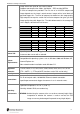
Installation and Operation Guide APPENDIX 4. –MPEG4 Bit Rate Lookup Table of IP camera 1. When frame rate is higher than 15 frames/second (15 is not including): Highest High Medium Low Lowest FULL D1 3 2.5 2 1.5 1 VGA 2.63 2.25 1.75 1.31 0.88 2CIF 1.5 1.25 1 0.75 0.5 Half VGA 1.31 1.13 0.88 0.67 0.44 CIF 0.75 0.63 0.5 0.38 0.25 QVGA 0.66 0.56 0.44 0.38 0.22 ZOOM * 2 3 2.5 2 1.5 1 ZOOM * 3 3 2.5 2 1.5 1 ZOOM * 4 3 2.5 2 1.5 1 2.
APPENDIX 5. –FAQ 1. How do I disable the DHCP function and use a static IP instead? A:Turn up the “DIP SWITCH” from “3” to “4” and change the relative network settings, the IP Address, NetMask and Gateway on the image web page. 2. Can the SD card be removed during recording? A:No, it cannot be removed until the recording comes to a single point. The POWER LED flashing light signals the SD card is operating. The green light indicates the unit is activating. The red light warns the SD card cannot be removed.