Operator’s Manual MM101332V1 Rev.
MM101332V1, Rev. K MANUAL REVISION HISTORY REV R1A R2A R3A D E F G DATE Mar/03 Jun/03 Feb/04 Feb/04 May/04 Nov/04 Jun/05 H J K Jun/05 Oct/05 Sep/06 REASON FOR CHANGE Initial release Added UHF—H (4W) and P25 functionality. Added UHF-L (4W). Added CE Mark and safety symbol conventions. Improved detail in operating instructions. Added RU101219V71-V73 information. Updated battery information and CE marking information.
MM101332V1, Rev. K NOTICE! This device is a RF transceiver intended for land mobile radio applications. The device may have use restrictions, which require that the national authority be contacted for any system licensing requirements, frequency use, allowable power level, etc.
MM101332V1, Rev. K TABLE OF CONTENTS Page 1 SAFETY TRAINING INFORMATION............................................................................................... 7 1.1 RF EXPOSURE GUIDELINES ................................................................................................... 7 1.2 ELECTROMAGNETIC INTERFACE/COMPATIBILITY ........................................................ 8 2 SAFETY SYMBOL CONVENTIONS................................................................................
MM101332V1, Rev. K 10.4.2 Scan Model .................................................................................................................... 32 NUISANCE DELETE (SYSTEM MODEL) ............................................................................. 32 BACKLIGHT ON/OFF .............................................................................................................. 32 CONTRAST ADJUST ................................................................................................
MM101332V1, Rev. K 11.9 11.8.4 Exiting Data Cells.......................................................................................................... 53 11.8.5 Scan Lockout Mode....................................................................................................... 53 11.8.6 Data Lockout Mode ....................................................................................................... 53 PAGE (P25 TRUNKING ONLY) ...............................................................
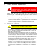
MM101332V1, Rev. K 1 SAFETY TRAINING INFORMATION The M/A-COM P7100IP portable radio generates RF electromagnetic energy during transmit mode. This radio is designed for and classified as “Occupational Use Only,” meaning it must be used only during the course of employment by individuals aware of the hazards and the ways to minimize such hazards. This radio is NOT intended for use by the “General Population” in an uncontrolled environment.
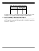
MM101332V1, Rev. K Table 1-1: RF Exposure Compliance Testing Distances RADIO FREQUENCY TESTED DISTANCES (worst case scenario) Body Face 800 MHz 1.1 cm 2.5 cm VHF (136-174 MHz) 1.1 cm 2.5 cm UHF-H (450-512 MHz) 1.1 cm 2.5 cm UHF-L (378-430 MHz) 1.1 cm 2.5 cm The information in this section provides the information needed to make the user aware of a RF exposure, and what to do to assure that this radio operates within the FCC RF exposure limits of this radio. 1.
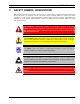
MM101332V1, Rev. K 2 SAFETY SYMBOL CONVENTIONS The following conventions are used to alert the user to general safety precautions that must be observed during all phases of operation, service, and repair of this product. Failure to comply with these precautions or with specific warnings elsewhere violates safety standards of design, manufacture, and intended use of the product. M/A-COM, Inc. assumes no liability for the customer’s failure to comply with these standards.
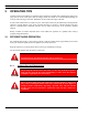
MM101332V1, Rev. K 3 OPERATING TIPS Antenna location and condition are important when operating a portable radio. Operating the radio in low lying areas or terrain, under power lines or bridges, inside of a vehicle or in a metal framed building can severely reduce the range of the unit. Mountains can also reduce the range of the unit. In areas where transmission or reception is poor, some improvement may be obtained by ensuring that the antenna is vertical.
MM101332V1, Rev. K Use only the supplied or approved antenna. Use of unauthorized antennas, modifications or attachments could cause damage to the radio unit and may violate FCC regulations. (Refer to Table 7-1: Options and Accessories.) 3.1.2 CAUTION 3.1.3 Electronic Devices RF energy from portable radios may affect some electronic equipment. Most modern electronic equipment in cars, hospitals, homes, etc. are shielded from RF energy.
MM101332V1, Rev. K 4 MARITIME CHANNELS As part of FCC Equipment Authorization Part 80 licensing, a maritime frequency usage plan has been included in this manual for reference. The antenna connector (between antenna and radio) is a nominal 50Ω impedance.
MM101332V1, Rev. K 5 BATTERIES The P7100 series portable radios use rechargeable, recyclable Nickel Cadmium (NiCd) or Nickel Metal Hydride (NiMH) batteries. Please follow the directions below to maximize the useful life of each type of battery. If the battery is ruptured or is leaking electrolyte that results in skin or eye contact with the electrolyte, immediately flush the affected area with water.
MM101332V1, Rev. K 5.4 CHANGING THE BATTERY PACK 5.4.1 Removing the Battery Pack Make sure the power to the radio is turned OFF. 1. Press the latch at the bottom of the battery pack. 2. Lift the battery pack from the bottom. 3. Remove the battery pack from the radio. Figure 5-1: Removing the Battery Pack 5.4.2 Attaching the Battery Pack Make sure the power to the radio is turned OFF. 1. Align the tab on the top of the battery pack with the slot at the top of the battery cavity. 2.
MM101332V1, Rev. K 5.5 BATTERY DISPOSAL In no instance should a battery be incinerated. Disposing of a battery by burning will cause an explosion. CAUTION RECHARGEABLE BATTERY PACK DISPOSAL – The product you have purchased contains a rechargeable battery. The battery is recyclable. At the end of its useful life, under various state and local laws, it may be illegal to dispose of this battery into the municipal waste stream.
MM101332V1, Rev. K 6 INTRODUCTION This manual describes how to use the P7100IP series portable radio. The P7100IP series radio is available without a front mounted keypad (P7130 – Select model), with a 6-button front mounted keypad (P7150 – Scan model) and with a DTMF front mounted keypad (P7170 – System model).
MM101332V1, Rev. K 7 OPTIONS AND ACCESSORIES Table 7-1 lists the Options and Accessories tested for use with the P7100IP series portable radios. Items for use with a specific band split or part number are noted. Refer to the maintenance manual or to M/A-COM’s Products and Services Catalog for a complete list of options and accessories, including those items that do not adversely affect the RF energy exposure. Always use M/A-COM authorized accessories (antennas, batteries, belt clips, speaker/mics, etc).
MM101332V1, Rev. K DESCRIPTION PART NUMBER Batteries (Wind Driven Rain) 7.5V NiCd Battery BKB 191 210/43 7.5V NiMH Battery BKB 191 210/44 Miscellaneous Accessories Speaker Mic KRY 101 1617/183 Speaker Mic Antenna Version Plus KRY 101 1617/184 Speaker Mic, Charger Compatible KRY 101 1617/185 Speaker Mic, Ant. Version, Charger Comp. KRY 101 1617/186 Speaker Mic, Immersible KRY 101 1617/283 Speaker Mic, Ant. Version, Immersible KRY 101 1617/284 Speaker Mic, Ant.
MM101332V1, Rev.
MM101332V1, Rev.
MM101332V1, Rev. K 8.1 CONTROLS The radio features two rotary control knobs and an emergency button mounted on the top of the radio. Push-To-Talk, option and monitor buttons are mounted on the side. The front mounted keypad has no buttons on the P7130IP Select model, six buttons on the P7150IP Scan model, and 15 buttons on the P7170IP System Radio. 8.1.1 Buttons and Knobs This section describes the primary function of the button and knob controls.
MM101332V1, Rev. K 8.1.2 Keypad (Scan and System Models Only) The keys on the Keypad have special functions and are labeled using a symbol or abbreviated word describing its primary function. Numeric entry is a secondary function of the keys. Each key is described in the following subsections. Figure 8-5: Scan Radio Front Panel KEY FUNCTION Primary Function: Allows the user to select system, or channels, depending on personality groups, programming. The buttons act as STEP UP or STEP DOWN.
MM101332V1, Rev. K Figure 8-6: System Radio Front Panel KEY FUNCTION Same as Scan Model. Same as Scan Model. 1-9, *, 0, # Selects a specific system. If the rotary knob is used to select the system and more than 16 systems are programmed in the radio, the key is used to select additional banks (groupings) of systems. These keys are used to place telephone interconnect and individual (unit-to-unit) calls. The keys operate like a normal telephone keypad.
MM101332V1, Rev. K 8.2 DISPLAY The radio Display is made up of 3 lines (see Figure 8-7). Lines 1 and 2 contain eight alphanumeric character blocks and are used primarily to display system and group names. Line 1 also displays radio status messages. The 3rd line is used primarily to display radio status icons. All three lines are used to display menu options when in the menu mode. If programmed, the display backlighting will illuminate upon power up or when radio controls are operated.
MM101332V1, Rev. K Table 8-1: Display Descriptions Steady – “Busy” transmitting or receiving Flashing – call queued Steady – special call mode (individual or telephone) Steady – during all radio transmissions Steady – transmit at low power If icon is not visible – transmit at high power Steady – battery charge indicator (refer to Figure 8-8) Flashing – Low battery indicator (refer to Figure 8-8) Steady – Indicates the current channel is set up as an analog channel.
MM101332V1, Rev. K Figure 8-9: Tri-Color LED 8.2.2 Tri-Color LED The Tri-Color LED changes color to indicate radio status and is visible from both the front and top of the radio (see Figure 8-9). The three colors of the LED and the status they represent are: Green: Receiving Red: Unencrypted transmission Orange: Encrypted transmission 8.2.3 Status Messages During radio operation, various radio Status Messages can be displayed. The messages are described below.
MM101332V1, Rev. K MESSAGE NAME DESCRIPTION SYSC OFF System Scan Features Off Trunked mode only. Indicates the System Scan features are disabled. LOW BATT Low Battery Battery voltage has dropped to the point to where the radio is no longer able to transmit. The radio will still receive calls until the battery is discharged beyond the point of operation at which time the radio will automatically shutdown. RXEMER Receive Emergency Trunked and P25 modes only.
MM101332V1, Rev.
MM101332V1, Rev. K 9 CONVENTIONAL OPERATION In addition to the features covered in the following BASIC OPERATION section, the following functions are for the conventional mode. The radio functions in the conventional mode when using conventional communications channels (non-trunked). 9.1 RECEIVING A CALL 1. Select desired conventional system and channel or turn scan ON and make sure desired channel is in scan list. 2.
MM101332V1, Rev. K 10 BASIC OPERATION 10.1 TURNING ON THE RADIO 1. Power ON the radio by rotating the POWER ON-OFF/VOLUME knob clockwise. A short alert signal (if enabled through programming) indicates the radio is ready to use. Refer to Figure 8-1 for location of the POWER ON-OFF/VOLUME KNOB. 2. The display shows the last selected system and group or a default system and group (depending on programming). 3. Adjust the POWER ON-OFF/VOLUME knob to the desired volume level. 4.
MM101332V1, Rev. K If system selection is programmed to the SYSTEM/GROUP/CHANNEL knob, direct access to systems will not be available. Pressing or will scroll through different sets of 16 systems each (banks) if more than 16 systems are programmed into the radio. The systems within each bank are then selectable via the SYSTEM/GROUP/CHANNEL knob as described previously in METHOD 1. Example: System: 1 = North 2 = South 3 = East 4 = West Group: 1 = Group 1 2 = Group 2 3 = Group 3 4 = Group 4 Press .
MM101332V1, Rev. K 10.4 MODIFY SCAN LIST 10.4.1 System Model 1. Press to toggle scan OFF and verify is not displayed. 2. Select group or channel. 3. Press once to remove group or channel from list. 4. Press once to add as a normal group or channel. Press twice to add as a Priority 2 group. Press three times to add as a Priority 1 group. 5. Press to re-start scanning. 10.4.2 Scan Model 1. Press to toggle scan OFF and verify is not displayed. 2. Select group or channel. 3.
MM101332V1, Rev. K 4. Press to toggle backlight ON and OFF. 5. Press to select new backlight setting. 10.7 CONTRAST ADJUST 1. Press to access the menu. 2. Press to scroll through menu until “CONTRAST” appears. 3. Press to select Contrast menu. 4. Press to adjust contrast setting from 1 - 4. 5. Press to select new contrast setting. 10.8 DECLARING AN EMERGENCY 1. Press and hold the red Emergency/Home button (the length of time is programmable; check with the system administrator).
MM101332V1, Rev. K 3. Press again to toggle between High and Low power. 4. “POWER = HIGH” or “POWER = LOW” will appear momentarily on the top line of the display. 10.10.2 Using the Pre-Programmed Option Button Press the Option button. “POWER = HIGH” or “POWER = LOW” will appear momentarily on the top line of the display. 10.11 MENU The Menu function accesses features that are not available directly from the keypad. The order and actual menu items available is configurable through programming.
MM101332V1, Rev. K 3. Press . The backlight menu item is activated. Line one shows the active menu item and its current parameter setting. Line two shows the currently selected system or group name (see Figure 10-2). Figure 10-2: Backlight Menu Display 4. The menu item's parameter setting shown in the display can now be changed by using or . 5. Once the desired setting is reached press to store the value and return the menu option selection level.
MM101332V1, Rev. K Table 10-1: Menu Item Information FEATURE PARAMETER SETTING COMMENT Keypad Lock Menu Item: KEY LOCK Once Selected: LOCKED Locked Unlocked Locks the keypad. To unlock; press and release “M” then within 1 second press the option button (NOTE: this sequence is also a short cut to locking the keypad.) Backlight Adjust Menu Item: BCK LIGHT Once Selected: BCKL= OFF/ON Selects the light level for backlighting.
MM101332V1, Rev. K PRS - NAME XXXXXXXX Personality Name EEPR SIZ EEPROM Size RAM SIZ RAM Size FLSH SIZ Flash Size RF BAND Frequency Band HSD RATE Data Transfer Rate PRS VER Software Version DSP_ _RAM DSP Software Version FLSH - VER FLASH Software r - released, 01A - revision state M/A-COM (C) – 2004 Copyright Figure 10-3: Information Display 10.
MM101332V1, Rev. K 10.12.3 Private Mode The Private Mode allows the radio to transmit encrypted messages and receive clear or private transmissions. The radio transmits private if the group/channel is programmed for private operation and forced operation is pre-programmed. If autoselect operation is pre-programmed and the radio is in the Private Mode, the radio transmits in the mode of the received call if the hang time is active. If no hang time is active, the radio transmits private.
MM101332V1, Rev. K 10.12.3.2 Key Zero All cryptographic keys can be zeroed (erased from radio memory) by pressing the MONITOR/CLEAR button and while still pressing this button, press and hold the OPTION button. Press both buttons for 2 seconds. A series of beeps will begin at the start of the 2 second period and then switch to a solid tone after the keys have been zeroed. The display will indicate KEY ZERO.
MM101332V1, Rev. K Table 10-2: Transmit/Receive Mode Compatibility for Digital Voice Operation GROUP/CHANNEL PROGRAMMING (TRANSMIT) CLEAR RECEIVE DIGITAL RECEIVE PRIVATE RECEIVE CLEAR Yes No No DIGITAL Yes Yes No PRIVATE Yes No Yes* *assumes the proper cryptographic key is loaded Conventional Digital or encrypted channels require Channel Guard on the channel to operate correctly.
MM101332V1, Rev. K 11 TRUNKED OPERATION This section describes P25 Trunked and EDACS operation. 11.1 SCANNING TRUNKED GROUPS Groups that have been previously added to the scan list on a per system basis may be scanned. Each system's group scan list is retained in memory when the radio is powered OFF or when the battery pack is removed. The following procedures outline scan operations for trunked groups.
MM101332V1, Rev. K group will change to non-priority scanning. One of the following messages may be momentarily displayed: SCAN DIS The radio is not programmed to scan. FIXED P1 A Priority 1 group has been pre-programmed into the radio. A new Priority 1 group cannot be selected. FIXD LST A fixed scan list has been pre-programmed into the radio. It is not possible to change the list without reprogramming the radio.
MM101332V1, Rev. K 11.1.3 11.1.3.1 Deleting Groups from a Scan List Scan Model 1. With scan operation turned OFF, select the desired group to delete from the selected trunked system group scan list. 2. Press . The current status of the group is displayed for a time-out period. While the current status is displayed, press . until the group from the scan list is "blank". The sequence is "blank", , , ,"blank".
MM101332V1, Rev. K 11.2.2 Priority System Scan The radio can also be programmed for Priority System Scan. The priority system is the desired or preferred system. While receiving the control channel of the selected system, the radio will periodically leave the selected system and search for the control channel of the priority system. This is done at a programmable rate defined by the value in the Priority Scan Time control (unless the ProScan™ algorithm is enabled, as explained in the following sections).
MM101332V1, Rev. K 11.3 EMERGENCY OPERATION The radio's ability to declare an emergency, clear an emergency, remain locked on an emergency system and group, and the emergency audio and display freeze can each be enabled or disabled through programming. When an emergency is declared scanning will stop and restarts only after the emergency has been cleared. 11.3.1 Receiving an Emergency Call When receiving an Emergency Call on the selected group and system, an alert beep is heard and is displayed.
MM101332V1, Rev. K If a response is made by pressing the PTT to the call prior to the programmed call-back time-out, the call will automatically be directed to the originating unit. If a response is not made before the call-back timeout, the radio will return to normal receive display, and *WHC* will appear on the first line of the LCD. To respond after the call-back time-out, press the key. The radio's display will show the callers ID on the first line and WHCI=1 on the second line.
MM101332V1, Rev. K SYSTEM MODEL 1. To select a pre-stored individual phone number, enter the individual call mode using the key. is displayed. Then scroll through the list of stored numbers using the or key. 2. Press the PTT button; when the radio is clear to transmit, turns ON, turns OFF and the channel access tone sounds. Line one shows the called individual's name if found in the list of stored individuals or LID followed by the logical ID number of the unit being called.
MM101332V1, Rev. K Figure 11-3: Calls Received and Personality Lists The saved call list shows all ten storage locations. If no calls have been received, the saved call list will be empty and the pre-stored list will be available upon entering the individual call mode. key toggles the time stamp ON and OFF. The time stamp indicates how long ago the call was received.
MM101332V1, Rev. K 3. A telephone ring will be heard from the speaker. When someone answers the phone, press the PTT button and speak into the microphone. Release the PTT button to listen to the callee. Unsuccessful interconnect signaling returns the radio to the normal receive mode and the number remains displayed until the special call is cleared or the time-out expires or another group or system is selected. Terminate a call by pressing the CLEAR/MONITOR button.
MM101332V1, Rev. K 2. Overdial numbers are transmitted by entering the phone mode using the button. Press to enter the overdial select/entry mode and follow the selection mode rules to call up a stored number from the phone list. is displayed. Press PTT to send the overdial sequence once. If the number needs to be transmitted again it must be selected or entered again (this prevents unwanted numbers from being sent the next time the PTT button is pressed during the call).
MM101332V1, Rev. K 11.7 STATUS/MESSAGE OPERATION Status operation permits the transmission of a pre-programmed status condition to the P25 Trunked or EDACS site. Message operation permits the transmission of a pre-programmed message text to a P25 Trunked or EDACS site. 11.7.1 Status Operation To send a status condition, press the key followed by or key to select the pre-programmed status. STATUS and 0 through 9 pre-programmed status selections are available from the menu.
MM101332V1, Rev. K 11.7.5 Macro Key Operation Macro key operation permits the user to accomplish a series of keystrokes with a single "macro" keystroke. Each Macro Key is capable of executing up to twenty (20) keystrokes, to any push button input (i.e., keypad keys, OPTION button, etc.). Each macro key can be pre-programmed to activate when pressed or when released. A macro key may also be pre-programmed to change the key stroke sequence the next time the macro key is activated.
MM101332V1, Rev. K • Pressing the “no data” (ND) key toggles data state ON or OFF. • Clearing an emergency. (Valid only if the emergency caused “Data OFF” operation.) 11.8.4 Exiting Data Cells Under normal conditions, the radio enters the scan lockout mode and returns to the control channel after completion of a data call (transmit or receive).
MM101332V1, Rev. K 2. Press the PTT button. If the receiving radio receives the Page and responds, both radios will emit three high-pitched tones. 11.9.1.1 Direct Dial Page (System Mode Only) The following procedures describe how to initiate and complete a Direct Dial Page. 1. The ID is not stored in the pre-stored list of call IDs but the individual unit ID is known, it can be entered directly from the keypad. 2. Press and hold the PTT button.
MM101332V1, Rev. K 12 PROJECT 25 (P25) CONVENTIONAL OPERATION 12.1 GROUP CALLS IN P25 MODE 12.1.1 Transmitting a Group Call 1. Select the desired P25 system. (P25 icon will appear in display.) 2. Select the Talk Group/Conventional Channel. (Selected simultaneously using either the system/group/channel knob or the group key.) 3. Press and hold the PTT. 4. When a grant tone is received (if enabled through programming) speak into the microphone. 5. Release PTT and wait for response. 12.1.
MM101332V1, Rev. K 12.3 EMERGENCY GROUP CALLS IN P25 MODE There is no method available for a system-wide Emergency clear. An emergency group call must be cleared on each individual radio. 12.3.1 Declaring an Emergency Group Call 1. Select the desired P25 system and Talk Group/Channel. 2. Press the red emergency button on the top of the radio. The radio will broadcast a short emergency transmission with the emergency bit set. “TXEMER” will appear in the display of the transmitting radio. 3.
MM101332V1, Rev. K 13 RADIO TEXTLINK OPERATION (EDACS ONLY) Radio TextLink provides a simple means of exchanging text messages. This section describes how to send messages if the Radio TextLink feature is enabled. To send a text message: 1. Select SEND MSG with the and scroll through the list of pre-defined messages using the or keys. 2. Select the desired message with the key. 3. Using the or , scroll through the list of available IDs and select the desired ID with the key.
MM101332V1, Rev. K 14 OPERATION FOLLOWING WATER CONTACT If the P7100IP model radio has been immersed in water or if the microphone air path or speaker grill become clogged with water, follow instructions under “Radio Microphone” and “Radio Speaker” sections to assure the highest quality transmitted and received messages. 14.1 RADIO MICROPHONE In the event the P7100IP microphone air path becomes clogged with water, blow two quick successive breaths of air directly into the radio microphone air hole.
MM101332V1, Rev. K 15 IMMERSIBLE P7100IP PREVENTIVE MAINTENANCE Those P7100IP radios labeled “immersible” (see Figure 15-1) require periodic testing using specialized equipment to verify the radio’s watertight integrity. Preventive Maintenance for Immersion-Rated Radios CAUTION P7100IP model radios with Immersion Option HTMR must be serviced by a service center authorized and certified by M/A-COM to perform the necessary tests to verify watertight integrity.
MM101332V1, Rev. K 15.1 TECHNICAL ASSISTANCE – IMMERSIBLE P7100IP To preserve the watertight integrity of the P7100IP portable radio, the radio must be serviced by a service center authorized and certified by M/A-COM to perform the necessary tests to verify the watertight integrity. Use one of the following methods to locate the nearest service center authorized to service the radios warranted under Option HTMR. • Contact M/A-COM’s Technical Assistance Center (TAC) at 1-800-528-7711 (in the U.S.
MM101332V1, Rev. K 16 BATTERY WARRANTY A. M/A-COM, Inc. (hereinafter "Seller") warrants to the original purchaser for use (hereinafter "Buyer") that nickel-cadmium and nickel-metal hydride batteries supplied by Seller shall be free from defects in material and workmanship, and shall conform to its published specifications for a period of twelve (12) months from the date of purchase. B.
MM101332V1, Rev. K 17 WARRANTY A. M/A-COM, Inc. (hereinafter "Seller") warrants to the original purchaser for use (hereinafter "Buyer") that Equipment manufactured by or for the Seller shall be free from defects in material and workmanship, and shall conform to its published specifications. With respect to all non-M/A-COM Equipment, Seller gives no warranty, and only the warranty, if any, given by the manufacturer shall apply.
MM101332V1, Rev.
Tyco Electronics Wireless Systems Segment 221 Jefferson Ridge Parkway Lynchburg, Virginia 24501 (Outside USA, 1-434-385-2400) Toll Free 1-800-528-7711 www.macom-wireless.com Printed in U.S.A.