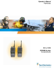
Operator’s Manual MM-008212-001 Rev.
MM-008212-001, Rev. A MANUAL REVISION HISTORY REV DATE - May/07 A Jul/07 REASON FOR REVISION Initial release. Added Lithium Ion battery pack tamper warning. M/A-COM Technical Publications would particularly appreciate feedback on any errors found in this document and suggestions on how the document could be improved. Submit your comments and suggestions to: Tyco Electronics Wireless Systems Segment M/A-COM, Inc.
MM-008212-001, Rev. A TABLE OF CONTENTS Page 1 SAFETY CONVENTIONS..................................................................................................................10 2 SAFETY TRAINING INFORMATION ............................................................................................11 2.1 RF EXPOSURE GUIDELINES .................................................................................................11 2.2 ELECTROMAGNETIC INTERFERENCE/COMPATIBILITY............................
MM-008212-001, Rev. A TABLE OF CONTENTS 8.7 8.8 8.9 8.10 8.11 8.12 8.13 8.14 8.15 8.16 8.17 8.18 8.19 8.20 8.21 8.22 8.23 8.24 8.25 8.26 4 Page 8.6.2 Talk Groups ...................................................................................................................37 OPENSKY DISPLAY OVERVIEW..........................................................................................37 8.7.1 Display’s Top Line ...............................................................................
MM-008212-001, Rev. A TABLE OF CONTENTS Page 9 EDACS OPERATION..........................................................................................................................54 9.1 TURNING ON THE RADIO .....................................................................................................54 9.2 CONTROLS ...............................................................................................................................54 9.2.1 Buttons and Knobs............................
MM-008212-001, Rev. A TABLE OF CONTENTS 9.24 9.25 9.26 9.27 9.28 Page 9.23.3 Dual-Tone Multi-Frequency: Overdial/Conventional Mode .........................................76 PROGRAMMABLE ENTRIES .................................................................................................77 9.24.1 Pre-Storing Individual and Telephone Interconnect Calls from the Keypad.................77 STATUS/MESSAGE OPERATION..........................................................................................
MM-008212-001, Rev. A TABLE OF CONTENTS Page 12 BASIC TROUBLESHOOTING........................................................................................................101 FIGURES Figure 4-1: Removing the Battery Pack......................................................................................................... 17 Figure 4-2: Attaching the Battery Pack..........................................................................................................
MM-008212-001, Rev. A TABLE OF CONTENTS Page Table 8-8: Emergency Calls vs. Emergency Alerts ....................................................................................... 50 Table 9-1: P5300 Keypad Functions.............................................................................................................. 55 Table 9-2: Display Descriptions .................................................................................................................... 58 Table 9-3: Alert Tones .....
MM-008212-001, Rev.
MM-008212-001, Rev. A 1 SAFETY CONVENTIONS The following conventions are used throughout this manual to alert the user to general safety precautions that must be observed during all phases of operation, service, and repair of this product. Failure to comply with these precautions or with specific warning elsewhere in this manual violates safety standards of design, manufacture, and intended use of the product. M/A-COM, Inc. assumes no liability for the customer’s failure to comply with these standards.
MM-008212-001, Rev. A 2 SAFETY TRAINING INFORMATION The M/A-COM P5300 portable radio generates RF electromagnetic energy during transmit mode. This radio is designed for and classified as “Occupational Use Only,” meaning it must be used only during the course of employment by individuals aware of the hazards and the ways to minimize such hazards. This radio is NOT intended for use by the “General Population” in an uncontrolled environment.
MM-008212-001, Rev. A • As noted in Table 2-1, ALWAYS keep the device and its antenna AT LEAST 2.8 cm (1.1 inch) from the body and at least 2.5 cm (1.0 inch) from the face when transmitting to ensure FCC RF exposure compliance requirements are not exceeded. However, to provide the best sound quality to the recipients of your transmission, M/A-COM recommends you hold the microphone at least 5 cm (2 inches) from mouth, and slightly off to one side.
MM-008212-001, Rev. A 3 OPERATING TIPS Antenna location and condition are important when operating a portable radio. Operating the radio in low lying areas or terrain, under power lines or bridges, inside of a vehicle or in a metal framed building can severely reduce the range of the unit. Mountains can also reduce the range of the unit. In areas where transmission or reception is poor, some improvement may be obtained by ensuring that the antenna is vertical.
MM-008212-001, Rev. A 3.1.3 3.1.4 Aircraft • Always turn off a portable radio before boarding any aircraft! • Use it on the ground only with crew permission. • DO NOT use while in-flight!! Electric Blasting Caps To prevent accidental detonation of electric blasting caps, DO NOT use two-way radios within 1000 feet of blasting operations. Always obey the "Turn Off Two-Way Radios" signs posted where electric blasting caps are being used. (OSHA Standard: 1926.900) 3.1.
MM-008212-001, Rev. A 4 BATTERIES The P5300 series portable radios use rechargeable, recyclable Nickel Cadmium (NiCd), Nickel Metal Hydride (NiMH), or Lithium Ion (Li Ion) batteries. Please follow the directions below to maximize the useful life of each type of battery. Do not disassemble or modify Lithium Ion battery packs. The Lithium Ion battery packs are equipped with built-in safety and protection features.
MM-008212-001, Rev. A Always use M/A-COM authorized chargers and conditioners. Use of unauthorized chargers and conditioners may void the warranty. CAUTION 4.1.3 Additional Information For more information regarding the proper care of portable radio batteries or establishing a battery maintenance program, refer to ECR-7367 which may be ordered by calling toll free 1-800-368-3277, then select option 7. 4.2 CHARGING BATTERY PACKS Battery chargers are available from M/A-COM with nominal charge times.
MM-008212-001, Rev. A Do NOT leave any M/A-COM rechargeable batteries in a charger for more than a few days. 4.4 CHANGING THE BATTERY PACK 4.4.1 Removing the Battery Pack Make sure the power to the radio is turned OFF. CAUTION Although the P5300 has been designed to tolerate changing the battery pack without turning power off, M/A-COM, Inc. recommends turning the radio off before changing battery packs to ensure safety and best operation. 1.
MM-008212-001, Rev. A 4.4.2 Attaching the Battery Pack Make sure the power to the radio is turned OFF. 1. Align the tabs at each side on the bottom of the battery pack with the slots at the bottom of the battery cavity . 2. Push the top of the battery pack down until the latches click to attach the battery to the radio. 3. Tug gently to verify that the latches are secure and the battery pack is properly attached to the radio. Figure 4-2: Attaching the Battery Pack 4.
MM-008212-001, Rev.
MM-008212-001, Rev. A 5 INTRODUCTION The P5300 series portable radio is available in two models: the P5350 Scan model with a limited 6-button front-mounted keypad and the P5370 System model with a 15-button DTMF front-mounted keypad. The 900 MHz P5300 portable radio delivers end-to-end digital voice and IP data communications.
MM-008212-001, Rev. A 6 OPTIONS AND ACCESSORIES Table 6-1 lists the Options and Accessories tested for use with the P5300 series portable radios. Refer to the maintenance manual or to M/A-COM’s Products and Services Catalog for a complete list of options and accessories, including those items that do not adversely affect the RF energy exposure. Always use M/A-COM authorized accessories (antennas, batteries, belt clips, speaker/mics, etc).
MM-008212-001, Rev.
MM-008212-001, Rev. A 7 USER INTERFACE This section describes the primary user interface; the buttons, knob controls, indicators, and display.
MM-008212-001, Rev. A 7.1 CONTROLS 7.1.1 Buttons and Knobs The P5300 portable radios feature two rotary control knobs, an emergency button, and a dual-position A/B switch located on the top of the radio (Figure 7-2). The Push-To-Talk (PTT) button and two option buttons are located on the side (Figure 7-3).
MM-008212-001, Rev. A The functions of the button and knob controls vary depending on the mode of operation. The primary functions of the button and knob controls when in the OpenSky mode of operation are listed in the following paragraphs. The functions while in other modes are discussed in later sections. POWER ON-OFF/VOLUME KNOB Applies power to the radio and adjusts audio volume. Rotating the control clockwise applies power to the radio.
MM-008212-001, Rev. A 7.1.2 Keypad The front mounted keypad of the P5350 “Scan” model has six buttons and P5370 “System” model has 15 buttons. Refer to Figure 7-4: P5350 “Scan” Radio Front Panel and Figure 7-5: P5370 “System” Model Front Panel, respectively.
MM-008212-001, Rev. A Alpha-numeric character entry is the function of most of the P5300 keypad keys in the OpenSky mode of operation. In addition, the (*) and (#) keys are also available. The function of each key is described in Table 7-1 and the following section. Table 7-1: P5300 Front Keypad Functions KEY FUNCTION Primary function: Acts much as an “enter” button to activate a selection.
MM-008212-001, Rev. A 7.1.3 Display The P5300 display is made up of 3 lines. Lines 1 and 2 contain twelve alpha-numeric character blocks each. The 3rd line also contains twelve blocks, each used to display radio status icons. If programmed, the display backlighting will illuminate upon power up or when radio controls are operated. Specific display characteristics will be discussed in following sub-sections. Figure 7-6: Sample Dwell Display OpenSky Mode 7.1.3.
MM-008212-001, Rev. A STATUS ICON DESCRIPTIONS Steady – transmit at low power. Appears in the 5th position of the display. If icon is not visible – transmit at high power. Steady – battery charge indicator (refer to Figure 10-4). Appears in the 12th position of the display. Flashing – Low battery indicator (refer to Figure 10-4). Steady – Indicates the current channel is set up as an analog channel. Appears in the 7th position of the display. Steady – group or channel in scan list.
MM-008212-001, Rev. A Figure 7-8: Tri-Color LED 7.1.4 Tri-Color LED The Tri-Color LED changes color to indicate radio status and is visible from both the front and top of the radio (see Figure 8-2). In OpenSky mode only two radio states are reflected by the LED and the status they represent are: Green: Receiving Red: Transmitting If the LED is flashing rapidly, the radio is receiving an emergency call.
MM-008212-001, Rev.
MM-008212-001, Rev. A 8 OPENSKY OPERATION Once an OpenSky system has been selected from the available systems on your P5300 series portable radio, the characteristics described in the following sections will govern operation. 8.1 CONTROLS The P5300 portable radio features two rotary control knobs, an emergency button, and a dual-position A/B switch located on the top of the radio. Refer to Figure 7-2: Top View.
MM-008212-001, Rev. A Table 8-1: Keypad Functions KEY FUNCTION Primary function: Acts much as an “enter” button to activate a selection. Secondary function: While in the “dwell display,” press repeatedly to scroll through and view status display (on 2nd line) for current profile, caller, received talk group, and channel. Scrolls thru available menu items (see Table 8-4). (P5350 only) (P5350 only) (P5350 only) Currently undefined. Currently undefined. Currently undefined.
MM-008212-001, Rev. A 8.2 RADIO STATUS ICONS Status Icons indicate the various operating characteristics of the radio. The icons show operating modes and conditions and appear on the third line of the display (see Table 8-2). Table 8-2: Status Icons Descriptions st Steady – Battery charge indicator. Appears in the 1 position in OpenSky mode. Flashing – Low battery indicator. Steady – Stealth mode is enabled, all tones and the display backlight are disabled, voice is still nd heard.
MM-008212-001, Rev. A 8.3 TRI-COLOR LED Figure 8-2: Tri-Color LED The Tri-Color LED changes color to indicate radio status and is visible from both the front and top of the radio (see Figure 8-2). In OpenSky mode only two radio states are reflected by the LED and the status they represent are: Green: Receiving Red: Transmitting If the LED is flashing rapidly, the radio is receiving an emergency call.
MM-008212-001, Rev. A If necessary, contact radio system administration personnel for log-in assistance and/or radio-specific log-in instructions. 8.5 LOG OFF THE NETWORK The *0## command de-registers the radio. Typically, this is automatically performed when powering down the radio. Using this method, the User ID is remembered by the radio so only the password is needed at next log-in. Log-off manually by pressing . If a user is logged in, it is necessary to log-off. 8.
MM-008212-001, Rev. A Profile 1 Profile 2 Profile 3 TG a TG d TG a TG b TG e TG d TG c TG f TG g TG x TG h TG y TG i TG z TG = Talk Group Figure 8-3: Personality Structure Example 8.6.2 Talk Groups A talk group represents a set of users that regularly need to communicate with one another. There can be any number of authorized users assigned to a talk group. Talk groups are established and organized by the OpenSky network administrator.
MM-008212-001, Rev. A 8.8 ALERT TONES The P5300 radio also provides audible Alert Tones or “beeps” to indicate the various operating conditions (see Table 8-3). Table 8-3: Alert Tones NAME TONE DESCRIPTION Call Queued one low tone/two high tones Call queued for processing Call Denied three short Radio is out of coverage area or requested talk group is active.
MM-008212-001, Rev. A 8.9 BASIC MENU STRUCTURE Table 8-4 illustrates the basic P5300 OpenSky menu structure. Menu items will vary depending upon system programming, radio hardware, and optional configurations. All menus except the dwell display menu can be turned off by network administration personnel. Menu Name Table 8-4: Basic P5300 OpenSky Menu Structure Radio Displays Usage Notes (first and second lines) To/From Dwell Display Engineering Display (Menu may not be available per programming.
MM-008212-001, Rev. A Menu Name Radio Displays Usage Notes (first and second lines) See Previous Page Selected Channel selected channel (Menu may not be available per radio programming) “ChannelMenu” Displays the current channel. Press display. to return to dwell (e.g. Normal, No Scan, Fixed) current scan mode “ScnModeMenu” Talk group Lock Out talk group “<” “LockOutMenu” Priority 2 Talk group current priority talk group “Priority2” or to choose Priority 2 talk group.
MM-008212-001, Rev. A 8.10 KEYPAD FUNCTION COMMANDS (P5370 ONLY) To perform a command from the keypad, use the keypad commands in Table 8-5. Table 8-5: Keypad Function Commands *0 *1 *4 *7 *8 *9 *32 *33 *61 *62 *60 8.11 Log-off command: *0## (logs the user off the system). See Section 8.5 for additional information. Key presses: Log-in command: *1 # ## (required for encryption). See Section 8.2 for additional information.
MM-008212-001, Rev. A 8.14 STEALTH MODE For some users, it is important to be able to turn off the radio’s display lights and side tones, but not the radio traffic. For example, in covert operations, lights and sounds could inadvertently expose an otherwise unobservable radio user. For this purpose, the radio has a Stealth feature that disables the radio display light, indicator light and audible side tones.
MM-008212-001, Rev. A 8.16 CHANGE OPERATING MODE 1. Press the 2. Press or or buttons to cycle through the menu until “Mode Menu” is displayed. to select the desired operating mode. 3. Press and use 4. Press again to make selection and return to the dwell display 8.17 or to select Y or N.
MM-008212-001, Rev. A Lock out is a listening (receive) function and only blocks received calls on locked out talk groups. Lock out does not affect transmit capability. “No Scan” and “Lock Out” do not apply to recent emergency lock outs. Only talk groups in the active profile can be locked out, since they are the only talk groups whose voice calls can be heard on the radio. Talk group lock out is a scan-related feature.
MM-008212-001, Rev. A The choice of scanning mode broadens or narrows the span of communications with all the groups in profiles you listen to, but does not affect your interaction with those groups you talk with. The scanning modes available for selection may be limited to a subset of the three scanning modes by the administrator. Table 8-6: Scan Modes SCAN MODE No Scan EXPLANATION Eliminates distractions. Full communications (listen and talk) with the active talk group.
MM-008212-001, Rev. A 8.20.2.2 Duration of Scanning Mode Selections Scanning Mode selections survive power down. At startup, the radio defaults to the scanning mode of set during last use. The last selection made remains in effect until a new selection is made from the Scan Mode menu. 8.20.3 Scanning Priority The following lists the scanning priority order (from highest to lowest): • Selected talk group in emergency state. • Default emergency group in emergency state. • Selected talk group.
MM-008212-001, Rev. A If a Selective Call is attempted without registration, “No Priv” is displayed. 8.21.1 Manually Dialing a Selective Call (P5370 Only) 1. Enter *8, the User ID number of the user being called, and the # key (no dashes or spaces). Note that this feature must be enabled by the administrator.
MM-008212-001, Rev. A 8.21.3 Accepting a Selective Call 1. The radio will ring (like a telephone), indicating you are receiving a Selective Call. 2. Press the button to accept the incoming selective call. 3. “CONNECT” will appear in the display, followed by “Lim 10 Min.” “SEL CALL” and the alias of the caller appear in the display once the call is established. 8.21.
MM-008212-001, Rev. A 8.22.2 Sending a Message The sending process has three steps. First select the destination radio’s User ID, then select the alert message, and finally send the message. 8.22.2.1 Selecting a Destination Using the Keypad (P5370 Only) 1. Using the keypad, enter *7, the keys. At the “AlertDst” prompt, enter the full User ID of the unit to send the message.
MM-008212-001, Rev. A 2. Press the key and or to select Y or N. key. The message will be deleted. 3. At the “Delete? Y” prompt, press the Received messages cannot be saved. 8.23 MAKING INTERCONNECT CALLS (P5370 ONLY) 1. Using the keypad, enter *9, followed by the telephone number being called, and the # key (no dashes or spaces). *9# Wait a couple of seconds and press and release the PTT button to initiate the call. An initial ring tone will sound to indicate signal call initiation.
MM-008212-001, Rev. A No emergency audio (voice) transmission (hot-mic) capability available (per programming by system administrator) 8.24.1 In addition to the Emergency Alert signal, the microphone goes hot for a predetermined length of time to allow for emergency audio (voice) transmission. The radio declaring the emergency has channel access priority. Note that the User can also use the PTT after the pre-determined hot-mic audio transmission, or during to extend the initial hot-mic audio transmission.
MM-008212-001, Rev. A The emergency dismiss timer is cleared when the emergency is cleared. 8.24.4 Clearing an Emergency Call or Alert 1. When the emergency ends, press and hold the red emergency button for three to five seconds to clear the emergency alert and call while on the active emergency talk group. The remove tone sounds when the emergency is cancelled. 2. The radio returns to your default selected talk group. The “EMERGENCY” display is removed from the main screen.
MM-008212-001, Rev.
MM-008212-001, Rev. A 9 9.1 EDACS OPERATION TURNING ON THE RADIO 1. Power ON the radio by rotating the POWER ON-OFF/VOLUME knob clockwise. A short alert signal (if enabled through programming) indicates the radio is ready to use. Refer to Figure 7-2 for location of the POWER ON-OFF/VOLUME KNOB. 2. The display shows the last selected system and group or a default system and group (depending on programming). 3. Adjust the POWER ON-OFF/VOLUME knob to the desired volume level. 4.
MM-008212-001, Rev. A EMERGENCY/ HOME BUTTON Automatically selects the pre-programmed Group/System by pressing and holding for a programmed duration. It can also be used to declare an emergency by pressing and holding for a programmed duration. The button must be preprogrammed for either operation, but not both. PTT BUTTON Push-To-Talk must be pressed before voice transmission begins. In trunked mode the radio’s ID is transmitted upon depression of the PTT button. (Refer to Figure 7-3.
MM-008212-001, Rev. A Figure 9-2: P5370 “System” Radio Front Panel KEY FUNCTION Primary Function: Accesses the pre-stored menu. Secondary Function: Activates a selected item within the menu. This is similar to an “Enter” key. Primary Function: Allows the user to scroll through available systems, groups, or channels, depending on personality programming. Secondary Function: Changes the selection for an item within a list. Primary Function: Refer to the separate key definitions within this table.
MM-008212-001, Rev. A 9.3 DISPLAY The radio Display is made up of 3 lines (see Figure 9-3). Lines 1 and 2 contain eight alphanumeric character blocks and are used primarily to display system and group names. Line 1 also displays radio status messages. The 3rd line is used primarily to display radio status icons. All three lines are used to display menu options when in the menu mode. If programmed, the display backlighting will illuminate upon power up or when radio controls are operated.
MM-008212-001, Rev. A 9.4 RADIO STATUS ICONS Status Icons indicate the various operating characteristics of the radio. The icons show operating modes and conditions and appear on the third line of the display (see Table 9-2). Table 9-2: Display Descriptions nd Steady – “Busy” transmitting or receiving. Appears in the 2 position of the display. Flashing – call queued th Steady – special call mode (individual or telephone). Appears in the 11 position of the display.
MM-008212-001, Rev. A 9.5 TRI-COLOR LED Figure 9-5: Tri-Color LED The Tri-Color LED changes color to indicate radio status and is visible from both the front and top of the radio (see Figure 9-5). The colors of the LED and the status they represent are defined below. Green: Receiving Red: Transmitting If the LED is flashing rapidly, the radio is receiving an emergency call. If the LED is flashing every ½ second, the selected talk group is in the emergency state (although not transmitting).
MM-008212-001, Rev. A MESSAGE NAME SYSC OFF System Scan Features Off Indicates the System Scan features are disabled. LOW BATT Low Battery Battery voltage has dropped to the point to where the radio is no longer able to transmit. The radio will still receive calls until the battery is discharged beyond the point of operation at which time the radio automatically shuts down. RXEMER Receive Emergency Indicates an emergency call is being received. This message will be flashing on line two.
MM-008212-001, Rev. A 9.8 ALERT TONES The P5300 radio provides audible Alert Tones or “beeps” to indicate the various operating conditions (see Table 9-3). Table 9-3: Alert Tones 9.
MM-008212-001, Rev. A Example: System: 1 = North 2 = South 3 = East 4 = West 9.10 Group: 1 = Group 1 2 = Group 2 3 = Group 3 4 = Group 4 1. Press . (South is the currently selected system.) 2. Press . (Press 4 to select “West” system.) 3. Press . (West is the newly selected system.) GROUP/CHANNEL SELECTION Several methods can be used to select a new group or channel. 9.
MM-008212-001, Rev. A 9.12 9.13 9.14 5. Press twice to add as a Priority 2 group. 6. Press three times to add as a Priority 1 group. 7. Press to re-start scanning. BACKLIGHT ON/OFF 1. Press to access the menu. 2. Press or 3. Press to select Backlight menu. 4. Press or 5. Press to select new backlight setting. to scroll through menu until “BCKLGHT” appears. to toggle backlight ON and OFF. CONTRAST ADJUST 1. Press to access the menu. 2. Press or 3. Press to select Contrast menu. 4.
MM-008212-001, Rev. A 9.16.1 Using the Menu Button 1. Press . or 2. Using the display. keys, scroll until the cursor (>) appears to the left of “TX POWER” in the again to toggle between High and Low power. 3. Press 4. “POWER = HIGH” or “POWER = LOW” will appear momentarily on the top line of the display. 9.16.2 Using the Pre-Programmed Option Button Press the Option button. “POWER = HIGH” or “POWER = LOW” will appear momentarily on the top line of the display. 9.
MM-008212-001, Rev. A Figure 9-7: Backlight Menu Item Selection Parameter . The backlight menu item is activated. Line one shows the active menu item and its 3. Press current parameter setting. Line two shows the currently selected system or group name (see Figure 9-8). Figure 9-8: Backlight Menu Display 4. The menu item's parameter setting shown in the display can now be changed by using 5. Once the desired setting is reached press level. or .
MM-008212-001, Rev.
MM-008212-001, Rev. A Table 9-5: Information Display RADIO ID XXXXXXXX LID in EDACS/EA In CONV it has no meaning. RAM SIZ RAM Size FLSH SIZ Flash Size RF BAND Frequency Band PERS VER Software Version DSP DATE Date DSP code was built. DSP TIME Time DSP code was built. DSP FEAT The DSP Features supported by the DSP code, in Hexadecimal.
MM-008212-001, Rev. A call or hang time is still active. Individual phone, all call, and emergency calls are transmitted clear if the digital mode is disabled or inoperative. If receiving an analog message trunked call, the radio responds in the analog mode during the hang time on the working channel. If receiving an analog I-Call, the radio responds in the analog mode during the hang time.
MM-008212-001, Rev. A 9.19.2 Adding Groups to a Scan List P5350 Model Radio 1. Scan must be OFF to add/delete groups to/from the scan list. If the Scan icon key to turn Scan OFF. 2. Select the desired group using the Voice group selection knob and/or the will display on line three. selected group is currently on the list, pressing is ON, press the or keys. If the 3. If the scan list status icon is blank ( ), the group can be added to the scan list by pressing the will be displayed on line three. 4.
MM-008212-001, Rev. A 5. Press a third time to set the group to Priority 1. A is displayed on line three. The priority level selection sequence only advances the group to next higher priority level and stops at priority level 1. To select a lower priority level, the group must be deleted from the scan list and then added back to the scan list. Each new group added to the scan list starts at the lowest priority.
MM-008212-001, Rev. A 9.20 SCANNING TRUNKED SYSTEMS The radio can be programmed with the following System Scan features. These features are automatically enabled when the radio is powered ON. A key or menu option is also defined to allow the System Scan features to be toggled during radio operation. The System Scan state will be maintained through system changes but will default to ON when the radio is powered ON.
MM-008212-001, Rev. A signal quality of the control channel for each site in its adjacent scan list. (The signal quality metric used for the ProScan algorithm is based on a combination of both Received Signal Strength Indicator (RSSI) and Control Channel Verification (CCV) measurements.) When the selected system degrades to a preprogrammed level, the radio will begin to look for a better control channel.
MM-008212-001, Rev. A The volume of the ring is adjustable through the volume control levels. If a response is made by pressing the PTT to the call prior to the programmed call-back time-out, the call will automatically be directed to the originating unit. If a response is not made before the call-back timeout, the radio will return to normal receive display, and *WHC* will appear on the first line of the LCD. key.
MM-008212-001, Rev. A P5370 Model Radio 1. To select a pre-stored individual phone number, enter the individual call mode using the displayed. Then scroll through the list of stored numbers using the or keys. key. is 2. Press the PTT button; when the radio is clear to transmit, turns ON, turns OFF and the channel access tone sounds. Line one shows the called individual's name if found in the list of stored individuals or LID followed by the logical ID number of the unit being called.
MM-008212-001, Rev. A Figure 9-11: Calls Received and Personality Lists The saved call list shows all ten storage locations. If no calls have been received, the saved call list will be empty and the pre-stored list will be available upon entering the individual call mode. key toggles the time stamp ON and OFF. The time stamp When in the saved call list, pressing the indicates how long ago the call was received.
MM-008212-001, Rev. A In half-duplex mode, only one person may talk at a time. The radio PTT button needs to be pressed in order to communicate to the individual called and released for the individual called to be heard. 9.23.2.2 Direct Dialing of Phone Calls (P5370 Model Only) 1. If the phone number is not stored in the pre-stored list of phone numbers, but the phone number is key, then enter the known, it can be entered directly from the keypad. Start by pressing the required number from the keypad.
MM-008212-001, Rev. A P5370 Model Radio 1. Follow the procedure in Section 9.23.2 to establish a connection to the telephone system or consult the system administrator for the procedure to access a dial tone on the trunked or conventional system. 2. Overdial numbers are transmitted using one of the following methods: METHOD 1: button. 1. Enter the overdial selection mode by pressing the or buttons to scroll through the list of stored numbers. is 2. Use the displayed.
MM-008212-001, Rev. A entries will accept up to 5 digits. The phone call list entries accept a combination of up to 31 digits and pauses. 4. Press and hold the key until the display changes indicating that the number has been stored. Repeat steps 1-4 to store additional numbers, to change numbers already stored, or to change the storage location of a number. 9.
MM-008212-001, Rev. A 9.25.2 Message Operation The following method can be used to transmit a Message using the Message Operation. 1. Press the key. 2. Press the corresponding pre-programmed 0 through 9 pre-programmed “message” key. If no message has been programmed for the selected number key, the radio will display NO ENTRY. A valid selection will permit the message to appear in the top line of the display and the message ID to appear in the second line of the display for a pre-programmed time.
MM-008212-001, Rev. A however, either data or voice is selected transparently by the operator through normal usage of the radio. Data communications is not supported in conventional mode. The radios can be connected to a Mobile Data Terminal (MDT) or to a host computer. Any RS-232 compatible device that supports the Radio Data Interface (RDI) protocol (Version 1.91 or greater) may be connected to the radio. Support for MDTs or host computers is a programmable option per radio.
MM-008212-001, Rev. A 9.28.5 Scan Lockout Mode Following the transmission or reception of a data call, if scan is enabled, scanning will stop temporarily. There are two independent pre-programmed times associated with this mode; one after a received data call and one after a transmitted data call. During this time the scan indicator will flash to indicate that scan is enabled but temporarily suspended.
MM-008212-001, Rev.
MM-008212-001, Rev.
MM-008212-001, Rev. A 10 CONVENTIONAL OPERATION The radio functions in the conventional mode when using conventional communications channels (nontrunked). 10.1 CONTROLS The radio features two rotary control knobs and an emergency button mounted on the top of the radio. Push-To-Talk and option buttons are mounted on the side. The front mounted keypad has six buttons on the P5350 Scan model and 15 buttons on the P5370 System model. 10.1.
MM-008212-001, Rev. A 10.1.2 Keypad The keys on the keypad have special functions and are labeled using a symbol or abbreviated word describing its primary function. Numeric entry is a secondary function of the keys. Each key is described in the following subsections. Figure 10-1: P5350 “Scan” Radio Front Panel KEY FUNCTION Primary Function: Allows the user to scroll through available systems, groups, or channels, depending on personality programming.
MM-008212-001, Rev. A Figure 10-2: P5370 “System” Radio Front Panel KEY FUNCTION Primary Function: Allows the user to scroll through available systems, groups, or channels, depending on personality programming. Secondary Function: Changes the selection for an item within a list. Primary Function: Accesses the pre-stored menu. Secondary Function: Activates a selected item within a list. This is similar to an “Enter” key. Primary Function: Refer to the separate key definitions within this table.
MM-008212-001, Rev. A 10.2 DISPLAY The radio display is made up of 3 lines (see Figure 10-3). Lines 1 and 2 contain eight alphanumeric character blocks and are used primarily to display system and group names. Line 1 also displays radio status messages. The 3rd line is used primarily to display radio status icons. All three lines are used to display menu options when in the menu mode. If programmed, the display backlighting will illuminate upon power up or when radio controls are operated.
MM-008212-001, Rev. A Steady (rotates clockwise) – scan mode enabled. Appears in the 9th position of the display. If icon is not visible – scan is disabled Steady – Channel Guard enabled. Appears in the 4th position of the display. If icon is not visible – Channel Guard is disabled Steady – Indicates the current channel is set up as a ProVoice or Aegis channel. Appears in the 7th position of the display.
MM-008212-001, Rev. A 10.4 STATUS MESSAGES During radio operation, various radio Status Messages can be displayed. The messages are described below. MESSAGE NAME DESCRIPTION TALKARND Talkaround Indicates the radio is operating on conventional channels in talkaround mode (no repeater). LOW BATT Low Battery Battery voltage has dropped to the point to where the radio is no longer able to transmit.
MM-008212-001, Rev. A 3. Adjust the POWER ON-OFF/VOLUME knob to the desired volume level. 4. Select the desired system and group. The display indicates the current system and group names. 5. The radio is now ready to transmit and receive calls. 10.7 SYSTEM SELECTION METHOD 1: From the control knob: If system selection is programmed to the SYSTEM/GROUP/CHANNEL SELECTION control knob, select a system by turning the knob to the desired system number position (1-16).
MM-008212-001, Rev. A METHOD 3: 10.9 (P5370 model radios only) Direct Access: Press to enter the group select mode. Press the numeric key mapped to the desired group. Press . The radio will move to the selected group. MODIFY SCAN LIST 10.9.1 1. Press P5370 Model to toggle scan OFF and verify is not displayed. 2. Select group or channel. 3. Press once to remove group or channel from list. 4. Press once to add as a normal group or channel. 5. Press twice to add as a Priority 2 group. 6.
MM-008212-001, Rev. A 10.12 10.13 CONTRAST ADJUST 1. Press to access the menu. 2. Press or 3. Press to select Contrast menu. 4. Press or 5. Press to select new contrast setting. to scroll through menu until “CONTRAST” appears. to adjust contrast setting from 1 - 4. DECLARING AN EMERGENCY 1. Press and hold the red Emergency/Home button (the length of time is programmable; check with the system administrator). 2. *TXEMER* will flash in the display, plus transmit icon and will be displayed.
MM-008212-001, Rev. A 10.16 MENU The Menu function accesses features that are not available directly from the keypad. The order and actual menu items available is configurable through programming. At radio power up, the menu item that is at the top of the menu list will always be displayed first. Subsequent access to the menu function will return the last menu item that was shown in the display and cursor position. 1. To enter the menu mode, press the key. 2.
MM-008212-001, Rev. A 3. Press . The backlight menu item is activated. Line one shows the active menu item and its current parameter setting. Line two shows the currently selected system or group name (see Figure 10-8). Figure 10-8: Backlight Menu Display 4. The menu item's parameter setting shown in the display can now be changed by using 5. Once the desired setting is reached press level. or .
MM-008212-001, Rev.
MM-008212-001, Rev. A Table 10-4: Information Display RADIO ID XXXXXXXX LID in EDACS/EA. In CONV it has no meaning. RAM SIZ RAM Size FLSH SIZ Flash Size RF BAND Frequency Band PERS VER Software Version DSP DATE Date DSP code was built. DSP TIME Time DSP code was built. DSP FEAT The DSP Features supported by the DSP code, in Hexadecimal.
MM-008212-001, Rev. A Individual phone, all call, and emergency calls are transmitted clear if the digital mode is disabled or inoperative. If receiving an analog I-Call, the radio responds in the analog mode during the hang time. When using the *WHC* feature to respond to an I-Call (after the hang time has expired), the call is transmitted in the mode defined by the system mode as programmed for the current system if the ID being called is not in the I-Call list.
MM-008212-001, Rev.
MM-008212-001, Rev.
MM-008212-001, Rev. A 11 TECHNICAL ASSISTANCE The Technical Assistance Center's (TAC) resources are available to help with overall system operation, maintenance, upgrades and product support. TAC is the point of contact when answers are needed to technical questions. Product specialists, with detailed knowledge of product operation, maintenance and repair provide technical support via a toll-free (in North American) telephone number. Support is also available through mail, fax and e-mail.
MM-008212-001, Rev. A 12 BASIC TROUBLESHOOTING Use Table 12-1 as a troubleshooting guide if the radio is not functioning properly. If additional assistance is required, contact a qualified service technician or call M/A-COM at 1-800-528-7711. Table 12-1: Troubleshooting SYMPTOM POSSIBLE CAUSE POSSIBLE SOLUTION Radio will not turn on Low battery charge Change the battery pack to a fully charged pack. No Audio Speaker volume is muted. Increase the volume level.
MM-008212-001, Rev. A BATTERY WARRANTY A. M/A-COM, Inc. (hereinafter "Seller") warrants to the original purchaser for use (hereinafter "Buyer") that nickel-cadmium and nickel-metal hydride batteries supplied by Seller shall be free from defects in material and workmanship, and shall conform to its published specifications for a period of twelve (12) months from the date of purchase. B.
MM-008212-001, Rev. A WARRANTY A. M/A-COM, Inc. (hereinafter "Seller") warrants to the original purchaser for use (hereinafter "Buyer") that Equipment manufactured by or for the Seller shall be free from defects in material and workmanship, and shall conform to its published specifications. With respect to all non-M/A-COM Equipment, Seller gives no warranty, and only the warranty, if any, given by the manufacturer shall apply.
Tyco Electronics Wireless Systems Segment 221 Jefferson Ridge Parkway Lynchburg, Virginia 24501 (Outside USA, 1-434-385-2400) Toll Free 1-800-528-7711 www.macom-wireless.com Printed in U.S.A.