Transport GT24 B2932 Service Engineer’s Manual
PREFACE Copyright This publication, including all photographs, illustrations, and software, is protected under international copyright laws, with all rights reserved. Neither this manual, nor any material contained herein, may be reproduced without written consent of the manufacturer-. Copyright 2007 Version 1.0 Disclaimer Information contained in this document is furnished by TYAN Computer Corporation and has been reviewed for accuracy and reliability prior to printing.
Federal Communications Commission (FCC) Notice for the USA Compliance Information Statement (Declaration of Conformity Procedure) DoC FCC Part 15: This device complies with part 15 of the FCC Rules Operation is subject to the following conditions: 1) This device may not cause harmful interference, and 2) This device must accept any interference received including interference that may cause undesired operation.
About this Manual This manual provides you with instructions on installing your Transport GT24, and consists of the following sections: Chapter 1: Provides an Introduction to the Transport GT24 B2932 barebones, packing list, describes the external components, gives a table of key components, and provides block diagrams of the system. Chapter 2: Covers procedures on installing the CPU, memory modules, an optional PCI-E card, and hard drives.
SAFETY INFORMATION Before installing and using the Transport GT24, take note of the following precautions: – Read all instructions carefully. – Do not place the unit on an unstable surface, cart, or stand. – Do not block the slots and opening on the unit, which are provided for ventilation. – Only use the power source indicated on the marking label. If you are not sure, contact the Power Company.
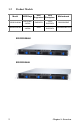
Table of Contents Chapter 1:Overview 1.1 1.2 1.3 1.4 1.5 About the TYAN Transport GT24 B2932 . . . . . . . . . . . . . . . . . . . 1 Product Models . . . . . . . . . . . . . . . . . . . . . . . . . . . . . . . . . . . . . . . . 2 Features . . . . . . . . . . . . . . . . . . . . . . . . . . . . . . . . . . . . . . . . . . . . . . 3 Unpacking . . . . . . . . . . . . . . . . . . . . . . . . . . . . . . . . . . . . . . . . . . . . 5 1.4.1 Accessories . . . . . . . . . . . . . . . . . . . . . . . . . . . . . .
3.5 3.6 3.7 3.8 3.9 Replacing the Slim DVD-ROM . . . . . . . . . . . . . . . . . . . . . . . . . . 44 Replacing the LED Control Board . . . . . . . . . . . . . . . . . . . . . . . . 46 3.6.1 M1003 LED Control Board Features. . . . . . . . . . . . . . . . . 48 3.6.2 M1003 LED Control Board Connector Pin Definition . . . 49 Replacing the M1012 Adapter Board . . . . . . . . . . . . . . . . . . . . . . 50 3.7.1 M1012 Adapter Board Features. . . . . . . . . . . . . . . . . . . . . 51 3.7.
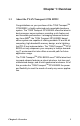
Chapter 1: Overview 1.1 About the TYAN Transport GT24 B2932 Congratulations on your purchase of the TYAN TransportTM GT24 B2932, a highly-optimized rack-mountable barebone system. The TYAN Transport GT24 B2932 offers the latest in dual processor server systems, providing a rich feature set and incredible performance.
1.
1.3 Features Enclosure • Industry 19” rack-mountable 1U chassis • Storage bay – (1) slim CD-ROM bay – (4) 3.5” HDD bays • Dimension: D 25.4 x W 17.2 x H 1.72 inch (645x436x43.6mm) Processors • Dual 1207-pin ZIF L1 sockets • Supports up to two AMD OpteronTM 2000/8000 series processors Chipset • • • • nVIDIA nForce Pro 3600 NEC nPD720400 SMSC DME5017 LSI 1068E Memory • Sixteen (16) 240-pin DDRII DIMM sockets (8 on CPU1 and 8 on CPU2).
Server Management Regulatory • Automatic fan speed control • Support Tyan Server Management (TSM) • Option TYAN SMDC M3291, IPMI v2.
1.4 Unpacking 1.4.1 Accessories If any items are missing or appear damaged, contact your retailer or browse to TYAN’s Web site for service: http://www.tyan.com. The Web site also provides information on other TYAN products, plus FAQs, compatibility lists, BIOS settings, and more.
Rail Kit Rear Front Mounting Bracket x 4 Sliding Brackets Front L-Bracket x 2 Rear L-Bracket x 2 Mounting Ears & Screws Screws Kit Sliding Rails x 2 FDD Kit FDD Cable FDD Installing Rails & Screws FDD Backplane Cable 6 Chapter 1: Overview
1.4.
Item Cable Set Model Number Quantity CCBL-0326 4 TF-SATA data cable, L=250mm HS/180-HS/180 CCBL-0340 1 TF-Front panel Control Board Cable HS2*14Pins/HS2*14 L=250mm(Flat Cable) CCBL-0409 1 TF-TYFP I Cable CCBL-0419 1 TF-TYFP II Cable CCBL-0433 1 TF-CD-ROM ATA66 FLAT CABLE CCBL-0420 1 TF-CD-ROM Power cable S4P/S4P L=80mm CCBL-0652 1 TF-FAN CABLE L=160mm CCBL-0493 1 TF- SAS HDD Fail Cable (B2932G24W4H SKU) CCBL-0310 1 TF-PWR CORD; US, 125V, 18AWGX3C CCBL-0300 1 TF-PWR CORD; EU,
1.5 About the Product This section contains the hardware diagrams and a block diagram of the GT24 system. 1.5.1 System Front View Warning LED Reset switch NMI switch HDD activity LED ID Switch Power LED ID LED Power switch 2 x LAN LEDs USB ports DVD-ROM Drive Hard Drive Bay x 4 1.5.
1.5.
Rear I/O LED LED Color State Description LAN1/LAN2 Linkage/ Activity (Left Side) Green Green OFF ON Blinking OFF 10Mb/100Mb/1000Mb linked 10Mb/100Mb/1000Mb activity No LAN linked and activity LAN1/LAN2 Linkage/ Activity (Right Side) Yellow 1 Blinking 2 Blinking 3 Blinking OFF 10Mb mode 100Mb mode 1000Mb mode NO LAN linked and activity Note: In 10 Mbps, the Right LED blinks yellow once in repeat and continuous action. In 100 Mbps, the Right LED blinks yellow twice in repeat and continuous action.
1.5.4 System Internal View B2932G24W4H 1 2 11 3 4 FAN5 FAN4 FAN3 FAN2 FAN1 FAN7 FAN6 5 6 7 10 9 8 1. PCI-Slot (with riser card M2083) 2. EPS 12V Power Supply 3. CPU Sockets 4. System Fans (Top-Right to left: FAN1, FAN2, FAN3, FAN4, FAN5; Bottom-Right to left: FAN6, FAN7) 12 5. 6. 7. 8. 9. 10. 11.
B2932G24V4H 1 2 11 3 FAN5 FAN4 FAN3 FAN2 FAN1 FAN7 FAN6 4 5 6 7 10 9 8 1. PCI-Slot (with riser card M2083) 2. EPS 12V Power Supply 3. CPU Sockets 4. System Fans (Top-Right to left: FAN1, FAN2, FAN3, FAN4, FAN5; Bottom-Right to left: FAN6, FAN7) Chapter 1: Overview 5. 6. 7. 8. 9. 10. 11.
DDR2 SDRAM 3 DDR2 SDRAM 2 SAS * 8 Channel A LSI CPU2 Secondary CPU AMD Socket Processor 16 x 16 HyperTransport PCI 32/33 PCI-Express X8 L1 F VGA ATI ES1000 B2932 G24 W4H SKU Only SAS1068E Channel B DDR2 SDRAM Interface PCI slot DDR2 SDRAM 4 DDR2 SDRAM Interface PCI Bus Super IO SCH5017 LPC L0 F BIOS Channel A Channel B DDR2 SDRAM Interface COM2 COM1 FLOPPY KB/MS Marve11 88E1121 RGMII 16 x 16 HyperTransport MCP55 Pro CPU1 Primary CPU L1 AMD Socket Processor DDR2 SDRA
1.5.6 S2932 Board Parts, Jumpers, and Connectors JP7 - Clear CMOS Jumper Pin 1-2 closed: Normal (Default) Pin 2-3 closed: Clear CMOS JP1/JP2 - PCI-X1/PCI-X2 Speed Setting Jumper Pin 1-2 closed: 133MHz Pin 2-3 closed: 100MHz JP3/JP4 - ASF2.0/SMDC Select Jumper Pin 1-2 closed: ASF2.
16 Chapter 1: Overview
Chapter 2: Setting Up 2.0.1 Before You Begin This chapter explains how to install the CPU, CPU heatsink, memory modules, and hard drives. Instructions on inserting a PCI-E card are also given. Take note of the precautions mentioned in this section when installing your system. 2.0.2 Work Area Make sure you have a stable, clean working environment. Dust and dirt can get into components and cause malfunctions. Use containers to keep small components separated.
2.0.4 Precautions Components and electronic circuit boards can be damaged by discharges of static electricity. Working on a system that is connected to a power supply can be extremely dangerous. Follow the guidelines below to avoid damage to the Transport GT24 or injury to yourself. • Ground yourself properly before removing the top cover of the system. Unplug the power from the power supply and then touch a safely grounded object to release static charge (i.e. power supply case).
2.1 Rack Mounting After installing the necessary components, the Transport GT24 can be mounted in a rack using the supplied rack mounting kit. Rack mounting kit Sliding Rails x 2 Sliding Brackets x 4 (Front x 2, Rear x 2) Mounting Ears (including screws) x 2 Screws Kit x 1 Mounting Brackets x 4 2.1.1 Installing the Server in a Rack Follow these instructions to mount the Transport GT24 into an industry standard 19" rack.
Installing the Inner Rails to Chassis 1. Screw the mounting ear to each side of Transport GT24 as shown using 2 screws from the supplied screws kit. Mounting Ears 2. Draw out the inner rails from rail assembly. Install inner rails to left and right sides of chassis using 1 M4-4L(A) screw for each side. Installing Outer Rails to the Rack 3. Measure the distance between inner side of the front and rear mounting brackets in the rack.
4. Locate the front and rear brackets. Rear Bracket x2 Front Bracket x2 5. Secure the front bracket to outer rail with 2 M4-4L(A) screws. 6. Reserve the distance same as in Step 2 on rear bracket. Secure the rear bracket to outer rail with 2 M4-4L(A) screws. 7. Secure the outer rail to the rack using 2 brackets and 4 M5-8L(B) screws for each side. Secure the mounting brackets from inside, not outside, of the rack.
Rackmounting the Server 8. Draw out the middle rail to the latch position. 9. Lift the chassis and then insert the inner slide rails into the middle rails. 10. Push the chassis in and press the latch key (A). Then push the whole system into the rack (B).
11. Secure the mounting ears of chassis to the rack with 2 M5-15L(C) screws. NOTE: To avoid injury, it is strongly recommended that two people lift the Transport GT24 into the place while a third person screws it to the rack.
2.2 Installing Motherboard Components This section describes how to install components on to the motherboard, including CPU, memory modules and PCI-E card. 2.2.1 Removing the Chassis Cover Follow these instructions to remove the Transport GT24 chassis cover. 1. Release the screw on the back side. Then slide the chassis cover in the direction of arrow. 2. Lift the cover off.
2.2.2 Installing the CPU, Heatsink and Air Duct Follow these instructions to install the CPU, CPU heatsink and air duct. 1. After removing the pre-installed air duct, locate the CPU sockets. 2. Take off the CPU protection cap. 3. Pull the CPU lever up to unlock the CPU socket.
4. Open the socket in the direction as shown. 5. Place the CPU in the CPU socket, ensuring that pin 1 is located as shown below. 6. Close the socket and press the CPU socket lever down to secure the CPU.
7. Place the heatsink on top of the CPU and screw into place as shown. 8. Place and screw the air duct back.
2.2.3 Installing the Memory Follow these instructions to install the memory modules on the motherboard. 1. Locate the memory slots on the motherboard. 2. Press the memory slot locking levers in the direction of the arrows as shown in the following illustration. 3. Align the memory module with the slot. The module has indentations that align with notches in the slots.
4. Insert the memory module into the slot as shown. When inserted properly, the memory slot locking levers lock automatically onto the indentations at the ends of the module. Attention When Installing the Memory! Please be noticed always install memory DIMMs in pairs starting from CPU1_DIMM0 and CPU1_DIMM1 and CPU2_DIMM0 and CPU2_DIMM1.
Refer to the table for supported DDR populations, and check the user’s manual for the details.
2.2.4 Installing a PCI-E Card There is one PCI-E slot on the rear panel of GT24. Refer to the procedures below for PCI-E installation. 1. Push the tab of PCI-E slot on the rear panel in the direction as shown to release the bracket. 2. Move the bracket to right as shown. 3. Locate the pre-installed PCI-E riser.
4. Insert the PCI-E card as shown. 5. Push the tab of PCI-E slot in the direction as shown to fix PCI-E card.
2.3 Installing the Hard Drives The TYAN Transport GT24 barebone system supports SAS/SATA hard drives. Follow these instructions to install a SAS/SATA hard drive for model GT24 B2932. 1. Press the locking lever latch in the direction of arrow (A) and then pull the locking lever open (B). B A 2. Slide the drive tray out. 3. Place a hard drive into the drive tray.
4. Using 4 HDD screws to secure the HDD. 5. Reinsert the drive tray into the chassis (A), ensuring that the drive tray is completely inserted into the chassis (B). A B 6. Pressing the locking lever to secure the hard drive tray.
2.4 Installing the Slim FDD (Option) 1. Locate the two FDD rails and screws from the FDD kit. Secure the two rails to FDD using four screws. FDD Rails & Screws 2. Connect the FFC cable to FDD. 3. Using a screw driver to pull open the door of FDD tray. 4. Insert FDD module into the tray.
5. Connect the FFC cable to the connector on M1012 adapter board. 6. Locate the FDD cable from FDD kit. Connect the wrinkle side to the connector on M1012 adapter board. Refer to the picture below for the correct direction. For Mainboard For M1012 7. Connect the other side to the connector on motherboard.
Chapter 3: Replacing Pre-Installed Components 3.1 Introduction This chapter explains how to replace pre-installed components including the motherboard, LED control board, DVDROM drive, M1012 adapter board, SAS/SATA backplane, and power supply. Take note of the precautions in this section when installing your system. 3.1.1 Work Area Make sure you have a stable, clean working environment. Dust and dirt can get into components and cause malfunctions. Use containers to keep small components separated.
3.1.3 Precautions Components and electronic circuit boards can be damaged by static electricity. Working on a system that is connected to a power supply can be extremely dangerous. Follow the guidelines below to avoid damage to the Transport GT24 or injury to yourself. • Ground yourself properly before removing the top cover of the system. Unplug the power from your computer power supply and then touch a safely grounded object to release static charge (i.e. power supply case).
3.2 Disassembly Flowchart The following flowchart outlines the disassembly procedure.
3.3 Removing the Cover Before replacing any parts you must remove the chassis cover. Follow these instructions to remove the cover of the Transport GT24 chassis cover. 1. Release the screw on the back side. Then slide the chassis cover in the direction of arrow. 2. Lift the cover off.
3.4 Replacing Motherboard Components Follow these instructions to replace motherboard components, including the motherboard. 3.4.1 Disconnecting All Motherboard Cables Before replacing the motherboard or certain components, remove cables connected to the motherboard. Follow these instructions to remove all motherboard cabling. 1.
2. Disconnect DVD-ROM drive cable, SAS/SATA hard drive cables, USB, TYFP I, TYFP II, and Fan cable. Refer to the mainboard layout for the locations.
3.4.2 Removing the Motherboard Follow these instructions to remove the motherboard from the chassis when all add-on components have been removed. 1. Remove two screws securing the link-bar to the chassis. 2. Remove ten screws securing the motherboard to the chassis. 3. Remove the motherboard.
3.5 Replacing the Slim DVD-ROM Follow these instructions to replace the DVD-ROM. 1. Remove power and data cables from the slim DVD-ROM adapter. 2. Press the tab in the directions as shown to release the DVD-ROM drive. 3. The DVD-ROM drive will be freed from the drive bay after pressing the tab.
4. Remove two screws that secure DVD-ROM drive to the bracket. 5. Replace the DVD-ROM drive. 6. Secure DVD-ROM to the bracket using two screws. Then replace the unit into the drive bay and connect the DVDROM power and data cables.
3.6 Replacing the LED Control Board Follow these instructions to remove the LED control board. 1. Remove the two screws securing the LED control board to the chassis. 2. Lift the LED control board unit free from the chassis. 3. Unplug the USB cable from the connector.
4. Unplug the ribbon cable from the connector. 5. Remove the three screws securing the LED control board to the bracket. 6. Lift the LED control board free from the chassis. After replacement, insert the unit to the chassis following the above procedures in reverse.
3.6.
3.6.
3.7 Replacing the M1012 Adapter Board 1. Remove all the cables connected to the adapter board, including front panel, TYFP, FAN, and DVD-ROM power cables. Refer to page 47 for the location 2. Remove the six screws to release the adapter board.
3.7.
3.7.
J3 LAN/ID LED Connector 1 LAN1_LED+ 2 LAN1_LED- 3 LAN2_LED+ 4 LAN2_LED- 5 LAN3_LED+ 6 LAN3_LED- 7 ID_LED+ 8 ID_LED- 9 ID_SW+ 10 ID_SW- 11 KEY PIN 12 NC FAN Signal Related Connector Pin Definition NOTE: The FAN signal naming is based on HW circuit design only. It might be different from the system fan naming.
J13 Fan TACH Connector 1 GND 2 FAN1_TACH 3 GND 4 FAN2_TACH 5 GND 6 FAN3_TACH 7 KEY PIN 8 NC J14 Fan TACH Connector 1 GND 2 FAN1_TACH 3 GND 4 FAN2_TACH 5 GND 6 FAN3_TACH 7 GND 8 FAN4_TACH 9 GND 10 FAN5_TACH 11 GND 12 FAN6_TACH 13 GND 14 FAN7_TACH 15 GND 16 FAN8_TACH 17 GND 18 FAN9_TACH 19 GND 20 FAN10_TACH 21 KEY PIN 22 PWM J6 Fan Connector 54 1 FAN1_12VPWM 2 FAN1_TACH 3 GND 4 GND 5 FAN2_TACH 6 FAN2_12VPWM Chapter 3: Replacing Pre-Inst
J10 Fan Connector 1 FAN3_12VPWM 2 FAN3_TACH 3 GND 4 GND 5 FAN4_TACH 6 FAN4_12VPWM J11 Fan Connector 1 FAN5_12VPWM 2 FAN5_TACH 3 GND 4 GND 5 FAN6_TACH 6 FAN6_12VPWM J9 Fan Connector 1 FAN7_12VPWM 2 FAN7_TACH 3 GND 4 GND 5 FAN8_TACH 6 FAN8_12VPWM Chapter 3: Replacing Pre-Installed Components 55
J5 Fan Connector 1 FAN9_12VPWM 2 FAN9_TACH 3 GND 4 GND 5 FAN10_TACH 6 FAN10_12VPWM J15 & J16 LCM Connectors 1 LCM_+5V 2 LCM_SIN 3 KEY PIN 4 GND 5 LCM_+5VSB 6 LCM_SOUT JP1 Fan Input Select Connector Pin1 & Pin2 Close Fan PWM signal from J8 Pin2 & Pin3 Close Fan PWM signal from J4, J7 & J14 (Default) JP2 Fan Input Select Connector 56 Pin1 & Pin2 Close 0V Pin2 & Pin3 Close +5V (Default) Chapter 3: Replacing Pre-Installed Components
3.8 Replacing the SAS/SATA Backplane NOTE: The procedures for replacing SAS/SATA backplanes are the same. 1. Remove the 3 screws securing the adapter board to the chassis. 2. Grab the two labels to lift the adapter board.
3. Remove the ten screws that secure the bracket to the adapter board. 4. Release the adapter board free from the bracket. 5. Replace the unit to the chassis following the reverse procedures from step 1 to 4 after done.
3.8.
PW1 Power Connector PW2 Power Connector J3, SAS/SATA 3 Connector J7, SAS Fault LED Connector 60 J4, SAS/SATA 4 Connector J2, SAS/SATA 2 Connector J1, SAS/SATA 1 Connector Chapter 3: Replacing Pre-Installed Components
3.9 Replacing the Power Supply 1. Remove the two screws that secure the power supply to the chassis. 2. Remove the screw that secure the power supply to the chassis 3. Lift the power supply free from the chassis. 4. Place a new power supply in position in the chassis and secure in place with the three screws.
Appendix I: BIOS Differences The BIOS of B2932 is similar to the BIOS of S2932. There is only one menu different. You may refer to the attached motherboard manual for the complete BIOS information. The differences between B2932 and S2932 is on the “Advanced/Hardware Health Information” menu. See the following for the differences.
S2932 Advanced/Hardware Health Information BIOS Setup Utility Advanced Hardware Health Configuration H/W Health Function CPUFAN1, 2 FAN1,2 PWM Control FAN3, FAN4, FAN5 PWM Control FAN Fail LED Indicator Enables Hardware Health Monitoring Device.
Appendix II: Cable Connection Tables SAS/SATA Cable Table 1: GT24 B2932 HDD Drive Connect to Motherboard HDD1 SATA0/SAS0 HDD2 SATA1/SAS1 HDD3 SATA2/SAS2 HDD4 SATA3/SAS3 FAN Cable Table 2: System Fan to M1012 Adapter Board System Fan Connect to M1012 Fan 1 / Fan 6 J6 Fan Connector Fan 2 / Fan 7 J10 Fan Connector Fan 3 J11 Fan Connector Fan 4 J9 Fan Connector Fan 5 J5 Fan Connector Table 3: M1012 Adapter Board to Motherboard M1012 J14 Fan connector 64 Connect to Motherboard J63 Fan
Power Supply Cable Table 4: Power Supply to Motherboard Power Supply Connect to Motherboard P1 24-pin power cable PW1 24-pin connector P2 8-pin power cable PW2 8-pin connector P3 4-pin power cable PW3 4-pin connector Table 5: Power Supply to M1012 Adapter Board Power Supply P4 4-pin power cable Connect to M1012 PW2 4-pin connector The Other Cable Table 6: M1003 Front Panel Control Board Related Cables M1003 J1 USB connector Motherboard J41 M1003 J2 connector M1012 J2 connector Table 7: DVD-R
Table 10: M1012 Adapter Board to Motherboard M1012 66 Connect to Motherboard J1 Front Panel connector J64 TYFP I connector J3 LAN/ID cable J65 TYFP II connector
Appendix III: Installing SMDC Cards The following provides you with the information on installing SMDC cards. You may refer to the following for installing M3289 or M3290 into HDD tray or chassis. Screws List No. Screw Size Quantity A Flat #6-32 -5L 16 B B-type #6-32-5L 4 C Stand-off #6-32-13.
1. Fold up the cable. 2. a: Choose a HDD tray. b: Insert the cable into the rear of HDD tray. c: Pull the cable out. 3. Connect the cable to M3289.
4. Align M3289 in reverse with 4 “M1” stand-offs. Secure the SMDC with 4 screws as illustrated. 5. Secure M3289 onto HDD tray as illustrated. 6. Insert and secure the HDD tray. NOTE: For internal or dummy HDD tray, secure the HDD tray with 1 or 2 screws. 7. Arrange and connect the cable to SMDC connector on mainboard. Be careful not to block the air flow.
Installing M3290/M3291 into HDD tray 1. Secure a removable stand-off of 13.5mm to the location of “M2” stand-off as illustrated on SMDC bracket. 2. Secure M3290 in reverse to 4 “M2” stand-offs on bracket. 3. a: Choose a HDD tray. NOTE: Refer to the location of SMDC connector on mainboard for choosing a HDD tray. b: Secure SMDC to the HDD tray.
4. a: Inset the cable into the rear of HDD tray. b: Connect the cable to M3290. c: Insert and secure HDD tray. 5. Arrange and connect the cable to SMDC connector on mainboard. Be careful not to block the air flow.
Technical Support If a problem arises with your system, you should first turn to your dealer for direct support. Your system has most likely been configured or designed by them and they should have the best idea of what hardware and software your system contains. Hence, they should be of the most assistance for you.
3. Contact your dealer for help BEFORE calling TYAN. 4. Check the TYAN user group: alt.comp.periphs.mainboard.TYAN Returning Merchandise for Service During the warranty period, contact your distributor or system vendor FIRST for any product problems. This warranty only covers normal customer use and does not cover damages incurred during shipping or failure due to the alteration, misuse, abuse, or improper maintenance of products.