Thunder h2000M /// S3992-E Version 1.0 Copyright Copyright © TYAN Computer Corporation, 2007. All rights reserved. No part of this manual may be reproduced or translated without prior written consent from TYAN Computer Corp. Trademark All registered and unregistered trademarks and company names contained in this manual are property of their respective owners including, but not limited to the following. TYAN, Taro and Thunder h2000M are trademarks of TYAN Computer Corporation.
Table of Contents Chapter 1: Introduction 1.1 Congratulations 1.2 Hardware Specifications Chapter 2: Board Installation 2.1 Board Image 2.2 Block Diagram 2.3 Board Parts, Jumpers and Connectors 2.4 Tips on Installing Motherboard in Chassis 2.5 Installing the Processor(s) 2.6 Installing the Memory 2.7 Attaching Drive Cables 2.8 Installing Add-In Cards 2.9 Installing Optional SO-DIMM Modules 2.10 Connecting External Devices 2.11 Installing the Power Supply 2.12 Finishing Up Chapter 3: BIOS 3.
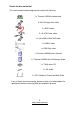
Check the box contents! The retail motherboard package should contain the following: 1x Thunder h2000M motherboard 1x 34-Pin floppy drive cable 4 x SATA cable 2 x S-ATA Power cable 1 x Ultra-DMA-100/66 IDE cable 1 x USB2.
NOTE 4 http://www.tyan.
Chapter 1: Introduction 1.1 - Congratulations You have purchased one of the most powerful server solutions available. The Thunder h2000M (S3992-E) is a high-end server motherboard, based on the ServerWorks BCM5780 & BCM5785 chipsets. It also includes the SMSC SCH4307 Super I/O and SMSC EMC6D103 Hardware Monitoring chipsets. This motherboard is designed to support up to two AMD Opteron™ Rev. F 2000 Series / Barcelona Quad core processors and DDRII 667/533 memory.
System Management • Two (2) EMC6D103 hardware monitoring IC • Eight (8) 3+1 fan headers support tachometer monitoring, six (6) of them with smart FAN control • Temperature and voltage monitoring • Watchdog timer support Expansion Slots • Two (2) PCI Express X16 slots (each w/ x8 signal) • Two (2) PCI-X 133/100MHz slots • One (1) PCI-X 100MHz slot • One (1) PCI 32-bit/33MHz, v2.
Chapter 2: Board Installation Precautions: The Thunder h2000M supports SSI, EPS12V type power supplies (24pin + 8pin) and will not operate with any other types. For proper power supply installation procedures see page 36. DO NOT USE ATX 2.x or ATXGES power supplies as they will damage the board and void your warranty. How to install our products right… the first time The first thing you should do is reading this user’s manual.
2.1- Board Image This picture is representative of the latest board revision available at the time of publishing. The board you receive may or may not look exactly like the above picture. The following page includes details on the vital components of this motherboard. 8 http://www.tyan.
2.2 - Block Diagram Thunder h2000M (S3992-E) Block Diagram 9 http://www.tyan.
2.3 - Board Parts, Jumpers and Connectors This diagram is representative of the latest board revision available at the time of publishing. The board you receive may not look exactly like the above diagram. Jumper Legend OPEN - Jumper OFF, without jumper cover CLOSED – Jumper ON, with jumper cover 10 http://www.tyan.
Jumper/Connector Function FAN5/FAN6 4-pin Fan Connector CPUFAN1/CPUFAN2/FAN1/ FAN2/FAN3/FAN4 4-pin Fan Connector with Speed Control J19 IPMB Connector J28 USB Front Panel Connector J30/J39/J40/J41 SATA Connectors J47 LAN & ID LED and ID Switch Connector J49 Front Panel Header JP1/JP2 SMDC/ASF2.0 Select Jumper (Close 1-2) Default, support ASF 2.
CPUFAN2 FAN6 FAN1 CPUFAN1 FAN5 FAN2 FAN4 FAN3 12 http://www.tyan.
FAN1~4/CPUFAN1~2: 4-pin Fan Connector with Speed Control CPUFAN1/FAN1~4 GND +1 2V Tac ho me ter 1 PWM Use these headers to connect the cooling fans to the motherboard to keep the system stable and reliable. This connector supports the tachometer monitoring and auto fan speed control.
J28 J18 J19 14 http://www.tyan.
J18: SMDC Connector 1 3 5 7 9 11 13 15 17 19 21 23 25 27 29 31 33 35 37 41 43 45 47 49 J33 LAD0 LAD2 GND1 GND2 GND3 GND4 I2C1DA I2C4CLK GND6 I2C3DA I2C2CLK 5VSB2 PWRBTN# RSTBTN# OEMBTN# EXTSMI# CPUNMI# SIO_RXD SIO_TXD LAD1 LAD3 LFRAME# PCI_CLK PCIRST# I2C1CLK GND5 I2C4DA I2C3CLK 5VSB1 I2C2DA GND7 PCIPME# COM_TXD COM_RXD SOL_CTRL GND8 COM_RTS# COM_CTS# SYSPWRGD SIO_RTS# SIO_CTS# OEMGPIO SERIRQ BMC_RST# GND12 SMALERTA# SMALERTB# BMC_DET# 2 4 6 8 10 12 14 16 18 20 22 24 26 28 30 32 34 36 38 40 For connect
J42 J47 J49 16 http://www.tyan.
J42: SO-DIMM Socket Connect SAS/SATA II Daughter Card (compatible with Tyan M9000-10, M7901/7902 Ultra 320 SCSI “TARO” card). J47: LAN & ID LED and ID Switch Connector 2 12 1 11 Use these pin definitions to connect a port to LAN & ID LED and ID Switch.
JP3 JP1 JP2 18 http://www.tyan.
JP1/JP2: SMDC/ASF2.0 Select Jumper JP1 JP2 1 1 3 (Default) - Support ASF2.0 3 JP1 JP2 1 1 3 3 Support SMDC card JP3: VGA Enable/Disable Jumper 1 (Default) - Enable VGA 3 1 Disable VGA 3 JP4: LAN3 Enable/Disable Jumper 1 (Default) - Enable LAN3 (Intel 82551) 3 1 Disable LAN3 3 JP5: S1/S2 PCI-X Mode Select Jumper JP8: P1 PCI-X Mode Select Jumper 3 (Default) - Based on card 1 3 Force to run at PCI mode (only 66 or 33 MHz) 1 19 http://www.tyan.
JP11 JP9 JP7 20 http://www.tyan.
JP7: S1/S2 PCI-X Frequency Select Jumper JP9: P1 PCI-X Frequency Select Jumper 3 (Default) - Based on card 1 3 Force to run at 100MHz or less 1 JP11: Clear CMOS Jumper 1 3 Clear 1 3 Normal (Default) Use this jumper when you have forgotten your system/setup password or need to clear the system BIOS settings.
2.4 - Tips on Installing Motherboard in Chassis Before installing your motherboard, make sure your chassis has the necessary motherboard support studs installed. These studs are usually metal and are gold in color. Usually, the chassis manufacturer will pre-install the support studs. If you are unsure of stud placement, simply lay the motherboard inside the chassis and align the screw holes of the motherboard to the studs inside the case.
2.5 - Installing the Processor(s) Your S3992-E supports the latest processor technologies from AMD. Check the TYAN website for latest processor support: http://www.tyan.com Figure 1. Exploded View of Thermal Solution AMD PIB Platforms based on AMD Socket F Processor 23 http://www.tyan.
Back plate Assembly The back plate is mounted on the backside of the motherboard and enhances local stiffness to support shock and vibration loads acting on the heat sink. The back plate assembly prevents excessive motherboard warpage in the area near the processor. Without a back plate, excessive warpage could cause serious damage to electrical connections of the processor socket and integrated circuit packages surrounding the processor. The back plate also serves as a stiffener plate for the LGA socket.
4. Locate four screw holes on socket and screw the socket to the PCB board. NOTE: Do not assemble CPU before securing socket with screws. 5. Inspect Socket F assembly to PCB. The Socket F must be tightly attached onto the PCB. There must NOT be any gap between stand off the PCB. 25 http://www.tyan.
Processor Installation The processor should be installed carefully. Make sure you are wearing an antistatic strap and handle the processor as little as possible. Follow these instructions to install your processor: 1. 3. Place the PCB such that the socket cam side faces you. Make sure the lever hook is on your top-left side. Use your left thumb and forefinger to hold the lever hook, then pull it to the left side to clear the retention tab. Rotate the lever to a fully open position. 4.
6. Remove the PnP cap. Use your left hand to hold the load plate. Then use your right thumb to remove the PnP cap from the load plate. With the package in the socket, the PnP cap removal process will not damage the contacts. 7. Close the socket. Rotate the load plate onto the package lid. Engage the load lever while pressing down lightly onto the load plate. Secure the lever near the hook end under the retention tab. 8. Repeat this procedure for the second processor if necessary. 27 http://www.tyan.
2.6 - Installing the Memory Before installing memory, ensure that the memory you have is compatible with the motherboard and processor. Only DDR2-667/533/400 DIMM modules are required. Check the TYAN Web site at: www.tyan.com for details of the type of memory recommended for your motherboard. The following diagram shows common types of DDR2 memory modules. Key points to note before installing memory: • • Only DDR2 667/533 /400 Registered ECC/non-ECC memory modules are supported.
Memory Installation Procedure Follow these instructions to install memory modules into the S3992-E. 1. Press the locking levers in the direction shown in the following illustration. 2. Align the memory module with the socket. The memory module is keyed to fit only one way in the socket. Key slot 3. Seat the module firmly into the socket by gently pressing down until it sits flush with the socket. The locking levers pop up into place. 29 http://www.tyan.
Key points to note before installing memory into Thunder h2000M: For optimal dual-channel DDR operation, always install memory in pairs beginning with CPU1_DIMMA3 and CPU1_DIMMB3. Memory modules of the same type and density are required for dual-channel DDR operation. Mismatched memory may cause system instability. Refer to the following table for supported DDRII populations.
2.7 - Attaching Drive Cables Attaching IDE Drive Cable Attaching the IDE drive cable is simple. The cable is “keyed” to only allow it to be connected in the correct manner. Attaching IDE cable to the IDE connector is illustrated below: Simply plug in the BLUE END of the IDE cable into the motherboard IDE connector, and the other end into the drive. Each standard IDE cable has three connectors, two of which are closer together.
The following pictures illustrate how to connect an SATA drive 1.SATA drive cable connection 2. SATA drive power connection 3. SATA cable motherboard connector 4. SATA drive power adapter Attaching Floppy Drive Cables Attaching floppy diskette drives are done in a similar manner to hard drives. See the picture below for an example of a floppy cable. Most of the current floppy drives on the market require that the cable be installed with the colored stripe positioned next to the power connector.
2.8 - Installing Add-In Cards Before installing add-in cards, it’s helpful to know if they are fully compatible with your motherboard. For this reason, we’ve provided the diagrams below, showing the most common slots that may appear on your motherboard. Not all of the slots shown will necessarily appear on your motherboard. Two 64-bit 133/100MHz PCI-X (white) slots One 64-bit 133/100MHz PCI-X (green) slot One 32-bit 33MHz PCI v2.
2.9 - Installing Optional SO-DIMM Modules Your Thunder h2000M S3992-E motherboard is equipped with an optional proprietary SODIMM connector. The SO-DIMM connector can be used for expansion cards to provide such features as, additional SAS/SATA II or SCSI support. For details of available expansions cards, visit the TYAN website at http://www.tyan.com. To install a SO-DIMM expansion card: 1. Open the spring levers as shown. 2.
Key slot 2.10 - Connecting External Devices Your motherboard supports a number of different interfaces for connecting peripherals. Some I/O ports may not be available with the board due to the different configurations. PS/2 Mouse/Keyboard LAN2 Port LAN1 Port Serial Port Integrated Video LAN3 Port USB x 2 Peripheral devices can be plugged straight into any of these ports but software may be required to complete the installation.
LAN3 LED Color Definition The onboard Ethernet port has green and yellow LEDs to indicate LAN status. The chart below illustrates the different LED states. 10/100 Mbps LAN3 Link/Activity LED Scheme Speed Left LED Right LED Link Green Off 10Mbps Activity Green (Blink) Off 10Mbps Link Green Green 100Mbps Activity Green (Blink) Green 100Mbps Left Right 2.11- Installing the Power Supply There are two power connectors on your Thunder h2000M.
Applying power to the board 1. Connect the EPS 12V 8-pin power connector. 2. Connect the EPS 12V 24-pin power connector. 3. Connect power cable to power supply and power outlet NOTE YOU MUST unplug the power supply from the wall outlet before plugging the power cables to motherboard connectors. 2.12 – Finishing Up Congratulations! You’re finished setting up the hardware aspect of your computer.
NOTE 38 http://www.tyan.
Chapter 3: BIOS 3.1 – BIOS Setup Utility With the BIOS setup utility, you can modify BIOS settings and control the special features of your computer. The setup utility uses a number of menus for making changes and turning the special features on or off. NOTE All menus are based on a typical system. The actual menus displayed on your screen may be different and depend on the hardware and features installed in your computer. To start the BIOS setup utility: a. Turn on or reboot your system b.
3.2 – BIOS Menu Bar The menu bar at the top of the windows lists these selections: Main Advanced PCI/PnP Boot Security Chipset Exit NOTE To configure basic system setups To configure the advanced chipset features To configure legacy Plug & Play or PCI settings To configure system boot order To configure user and supervisor passwords To configure chipset management features To exit setup utility Options written in bold type represent the BIOS setup default 3.
In Case of Problems If you discover that you have trouble booting the computer after making and saving the changes with the BIOS setup program, you can restart the computer by holding the power button down until the computer shuts off (usually within 4 seconds); resetting by pressing CTRL-ALT-DEL; or clearing the CMOS. The best advice is to only alter settings that you thoroughly understand. In particular, do not change settings in the Chipset section unless you are absolutely sure of the outcome.
3.4 – BIOS Main Menu The Main BIOS Menu is the first screen that you can navigate. The Main BIOS setup menu screen has two main frames. The left frame displays all the options that can be configured. "Grayed-out" options cannot be configured, options in blue can be changed. The right frame displays the key legend. Above the key legend is an area reserved for a text message. When an option is selected in the left frame, it is highlighted in white. Often, a text message will accompany it.
3.5 – BIOS Advanced Menu You can select any of the items in the left frame of the screen, such as Super I/O Configuration, to go to the sub menu for that item. You can display an Advanced BIOS Setup option by highlighting it using the keys. All Advanced BIOS Setup options are described in this section. The Advanced BIOS Setup screen is shown below. The sub menus are described on the following pages.
Feature Advanced Settings Option Description MPS Configuration Menu Item Configure the Multi-Processor Table PCI Express Configuration Menu Item Configure PCI Express L0 and L1 link power states. Remote Access Configuration Menu Item Configure Remote Access USB Configuration Menu Item Configure the USB support Device & PCI Slots Configuration Menu Item Onboard Devices and PCI AddOn Cards Enabled/Disabled 44 http://www.tyan.
3.5.1 CPU Configuration Sub-Menu You can use this screen to view CPU Configuration Menu. Use the up and down arrow (Ç/È) keys to select an item. Use the Plus and Minus (+/-) keys to change the value of the selected option. The settings are described on the following pages. Main Advanced BIOS Setup Utility PCI/PnP Boot Security CPU Configuration Module Version : XX.
Feature CPU Configuration Option Description Disabled This option should remain disabled for normal operation. The driver developer may enable it for the purpose of testing. GART Error Reporting Enabled Microcode Update Secure Virtual Machine Mode AMD PowerNow Enabled Enable CPU Microcode Update Disabled Enabled Enable/Disable Secure Virtual Machine Mode (SVM) Disabled Enable/disable the generation of ACPI_PPC, _PSS, and _PCT objects. Disabled Enabled 46 http://www.tyan.
3.5.2– IDE Configuration Sub-Menu You can use this screen to select options for the IDE Configuration Settings. Use the up and down keys to select an item. Use the and keys to change the value of the selected option.
3.5.2.1 – Primary/Secondary IDE Master/Slave Sub-Menu Main Advanced Primary IDE Master BIOS Setup Utility PCI/PnP Boot Security [Auto] [Auto] [Auto] [Auto] [Auto] [Auto] [Enabled] Type LBA /Large Mode Block (Multi-Sector Transfer) PIO Mode DMA Mode S.M.A.R.T. 32 Bit Data Transfer Type Option Auto Not Installed CD/DVD ARMD Disabled Auto Block (Multi-Sector Transfer) Disabled Auto 0~4 (at 1 interval) Auto S.M.A.R.T. Disabled Select the PIO Mode.
3.5.3 – Floppy Configuration Sub-Menu You can use this screen to specify options for the Floppy Configuration Settings. Use the up and down keys to select an item. Use the and keys to change the value of the selected option. The settings are described on the following pages. Main Advanced BIOS Setup Utility PCI/PnP Boot Security Exit Select the type of floppy drive connected to the system. Floppy Configuration Floppy A Floppy B Chipset [1.
3.5.4 – Super IO Configuration Sub-Menu You can use this screen to select options for the Super I/O settings. Use the up and down arrow (Ç/È) keys to select an item. Use the Plus and Minus (+/-) keys to change the value of the selected option Main Advanced BIOS Setup Utility PCI/PnP Boot Security Exit Allows BIOS to enable or disable Floppy Controller.
3.5.5 S-ATA Configuration Sub-Menu You can use this screen to view S-ATA Configuration Menu. Use the up and down arrow (Ç/È) keys to select an item. Use the Plus and Minus (+/-) keys to change the value of the selected option. The settings are described on the following pages.
3.5.6 –ACPI Configuration Sub-Menu Use this screen to select options for ACPI. Use the up and down arrow (Ç/È) keys to select an item. Use the Plus and Minus (+/-) keys to change the value of the selected option. A description of the selected item appears on the right side of the screen. The settings are described on this page. The screen is shown below. Main Advanced BIOS Setup Utility PCI/PnP Boot Security Feature Advanced ACPI Configuration [ACPI v2.
3.5.7 – Event Logging details Sub-Menu You can use this screen to view the Event Log Control Menu. This logs system events (such as CMOS clear, ECC memory errors, etc) and writes the log into NVRAM. Use the up and down arrow (Ç/È) keys to select an item. Use the Plus and Minus (+/-) keys to change the value of the selected option. The settings are described on the following pages.
3.5.8 – Hardware Health Configuration Sub-Menu You can use this screen to view the Hardware Health Configuration Settings. Use the up and down arrow (Ç/È) keys to select an item. Use the Plus and Minus (+/-) keys to change the value of the selected option. The settings are described on the following pages. Main BIOS Setup Utility PCI/PnP Boot Security Advanced Exit Enables Hardware Health Monitoring Device.
Feature Option Description Hardware Health Configuration FAN power duty cycle is auto dynamic programmed in selected temperature range. Disabled: Fan Power On. Enabled: Fan Power Duty Cycle=30%(40˚C)100%(60˚C), see CPU temperature Enabled CPU FAN1, FAN1, 2, 3 Power Control Disabled CPU FAN2, FAN4, 5, 6 Power Control FAN power duty cycle is auto dynamic programmed in selected temperature range. Disabled: Fan Power On. Enabled: Fan Power Duty Cycle=30%(40˚C)100%(60˚C), see mainboard temp.
3.5.8.1 – Mainboard Voltages Report Sub-Menu Main Advanced BIOS Setup Utility PCI/PnP Boot Security Chipset Exit Board Voltages Report CPU1 Vdimm CPU2 Vdimm CPU1 Vcore CPU2 Vcore +V3.3 (SB) +3VDU +V5 (SB) VCC +12V (for cpu1 vcore) +12V (for cpu2 vcore) : x.xxx V : x.xxx V : x.xxx V : x.xxx V : x.xxx V : x.xxx V : x.xxx V : x.xxx V : x.xxx V : x.xxx V 56 http://www.tyan.
3.5.9 MPS Configuration Sub-Menu You can use this screen to select MPS revision. Use the up and down arrow (Ç/È) keys to select an item. The settings are described on the following pages. Main Advanced BIOS Setup Utility PCI/PnP Boot Security Feature MPS Configuration MPS Revision Exit Select MPS Revision. MPS Configuration MPS Revision Chipset ← → Select Screen ↑↓ Select Item +/- Change Option F1 General Help F10 Save and Exit ESC Exit [1.4] Option Description 1.
3.5.10 PCI Express Configuration Sub-Menu You can use this screen to enable PCI Express support. Use the up and down arrow (Ç/È) keys to select an item. The settings are described on the following pages. Main Advanced BIOS Setup Utility PCI/PnP Boot Security Chipset Exit Enabled/Disabled PCI Express L0s and L1 link power states.
3.5.11 – Remote Access Configuration Sub-Menu You can use this screen to view the Remote Access Configuration Menu. This feature allows access to the Server remotely via serial port. Use the up and down arrow (Ç/È) keys to select an item. Use the Plus and Minus (+/-) keys to change the value of the selected option. The settings are described on the following pages.
Feature Option Description Configure Remote Access type and parameters Disable: Turns off the redirection Disabled after POST Boot Loader: Redirection is active during POST Redirection After BIOS and during Boot Loader. Boot Loader POST Always: Redirection is always active. ANSI Terminal Type Select the target terminal type. VT100 VT-UTF8 VT-UTF8 Combo Key Support Enabled Enable VT-UTF8 Combination key Support for ANSI/VT100 terminals.
3.5.12 – USB Configuration Sub-Menu You can use this screen to view the USB Configuration Menu. Use the up and down arrow (Ç/È) keys to select an item. Use the Plus and Minus (+/-) keys to change the value of the selected option. The settings are described on the following pages. Main Advanced BIOS Setup Utility PCI/PnP Boot Security Module Version – X.XX.X-XX.
3.5.13 Device & PCI Slots Configuration Sub-Menu You can use this screen to enable the onboard devices and PCI slots. Use the up and down arrow (Ç/È) keys to select an item. The settings are described on the following pages.
3.6 –BIOS PCI/PnP Menu You can use this screen to view PnP (Plug & Play) BIOS Configuration Menu. This menu allows the user to configure how the BIOS assigns resources & resolves conflicts. Use the up and down arrow (Ç/È) keys to select an item. Use the Plus and Minus (+/-) keys to change the value of the selected option. The settings are described on the following pages. Main Advanced BIOS Setup Utility PCI/PnP Boot Security Exit Clear NVRAM during System Boot.
Feature Advanced PCI/PnP Settings Clear NVRAM Option Description No Yes Clears NVRAM during system Boot. No: lets the BIOS configure all the devices in the system. Yes: lets the operating system configure Plug and Play (PnP) devices not required for boot if your system has a Plug and Play operating system. Yes Plug & Play OS No 32 This setting controls how many PCI clocks each PCI device can hold the bus before another PCI device takes over.
3.7 – BIOS Boot Menu You can display Boot Setup option by highlighting it using the Arrow (Ç/È) keys and pressing Enter. The settings are described on the following pages. Main Advanced BIOS Setup Utility PCI/PnP Boot Security Chipset Exit Boot Settings Configures settings during System Boot. Boot Settings Configuration ← → Select Screen ↑↓ Select Item Enter Go to Sub Screen F1 General Help F10 Save and Exit ESC Exit Boot Device Priority Removable Drives 3.7.
Feature Option Description Boot Settings Configuration Quick Boot Enabled Disabled Disabled Quiet Boot Enabled Add On ROM Display Mode Boot up Num-Lock PS/2 Mouse Support Force BIOS Keep Current On Off Enabled Disabled This option allows user bypass BIOS self test during POST. Disabled: displays normal POST messages. Enabled: displays OEM log instead of POST messages. Allows user to force BIOS/Option ROM of add-on cards to be displayed during quiet boot. Selects Power-on state for Numlock.
3.7.2 – Boot Device Priority Sub-Menu Use this screen to select options for the Boot Device Priority. Use the up and down arrow (Ç/È) keys to select an item. Use the Plus and Minus (+/-) keys to change the value of the selected option. Main Advanced BIOS Setup Utility PCI/PnP Boot Security Exit Specifies the boot sequence from the available devices.
3.7.3 – Removable Drives Sub-Menu Use this screen to select options for the Removable Drives. Use the up and down arrow (Ç/È) keys to select an item. Use the Plus and Minus (+/-) keys to change the value of the selected option. Main Advanced BIOS Setup Utility PCI/PnP Boot Security Exit Specifies the boot sequence from the available devices.
3.8 – BIOS Security Menu The system can be configured so that all users must enter a password every time the system boots or when BIOS Setup is entered, using either the Supervisor password or User password. The Supervisor and User passwords activate two different levels of password security. If you select password support, you are prompted for a one to six character password. Type the password on the keyboard. The password does not appear on the screen when typed. Make sure you write it down.
3.9 – BIOS Chipset Menu This menu allows the user to customize functions of the AMD Chipsets. North Bridge configuration contains options for Memory & CPU settings. South Bridge configuration contains options for SM Bus & USB. Additional configuration for the AMD8131 PCI-X Tunnel is available in the PCI-X Configuration Menu. Select a menu by highlighting it using the Arrow (Ç/È) keys and pressing Enter. The settings are described on the following pages.
3.9.1 – North Bridge Chipset Configuration Sub-Menu This menu gives options for customizing memory & Hypertransport settings. Select a menu by highlighting it using the Arrow (Ç/È) keys and pressing Enter. The settings are described on the following pages.
Feature Option NorthBridge Chipset Configuration Min Active RAS (Tras) Read only Row Precharge Time (Trp) Read only RAS/RAS Delay (Trrd) Row Cycle (Trc) Description This setting allows you to select the number of clock cycles allotted for the RAS pulse width, according to DRAM specifications. The less the clock cycles, the faster the DRAM performance. This item controls the number of cycles for Row Address Strobe (RAS) to be allowed to precharge.
3.9.1.1 – Memory Configuration Sub-Menu This menu has options for memory speed & latency. Use the up and down arrow (Ç/È) keys to select an item. Use the Plus and Minus (+/-) keys to change the value of the selected option.
Enabled : Configured to two singlechannel DRAM Controllers Disabled : Configured to a single dual-channel DRAM Controller Enabled Unganged Mode Support Power Down Enable Power Down Mode Disabled Enabled Enable or disable DDR power down mode Disabled Channel Set DDR power down mode Chip Select 74 http://www.tyan.
3.9.1.2 –ECC Configuration Sub-Menu This menu allows the user to configure ECC setup for system & DRAM. Use the up and down arrow (Ç/È) keys to select an item. Use the Plus and Minus (+/-) keys to change the value of the selected option. Main Advanced BIOS Setup Utility PCI/PnP Boot Security ECC Configuration [Good] [Enabled] [Enabled] [Enabled] [Enabled] [1.
DRAM BG Scrub Data Cache BG Scrub Disabled 40ns 80ns 160ns 320ns 640ns 1.28us 2.56us 5.12us 10.2us 20.5us 41.0us 81.9us 163.8us 327.7us 655.4us 1.31ms 2.62ms 5.24ms 10.49ms 20.97ms 42.00ms 84.00ms Disabled 40ns 80ns 160ns 320ns 640ns 1.28us 2.56us 5.12us 10.2us 20.5us 41.0us 81.9us 163.8us 327.7us 655.4us DRAM scrubbing corrects memory errors so later reads are correct. Doing this while memory is not being used improves performance.
L2 /L3 Cache BG Scrub Disabled 40ns 80ns 160ns 320ns 640ns 1.28us 2.56us 5.12us 10.2us 20.5us 41.0us 81.9us 163.8us 327.7us 655.4us Allows the L2/L3 Data Cache RAM to be corrected while idle. 77 http://www.tyan.
3.9.1.3 DRAM Timing Configuration Sub-Menu This menu allows the user to configure DRAM Timing. Use the up and down arrow (Ç/È) keys to select an item. Use the Plus and Minus (+/-) keys to change the value of the selected option.
3.9.1.4 IOMMU Option Sub-Menu This menu has options for IOMMU. Use the up and down arrow (Ç/È) keys to select an item. Use the Plus and Minus (+/-) keys to change the value of the selected option. Main Advanced IOMMU Mode BIOS Setup Utility PCI/PnP Boot Security Chipset Exit Set GART size in systems without AGP, or disable altogether. Some OSes require valid GART for proper operation, If AGP is present, select appropriate option to ensure proper AGP operation.
3.9.2 – HT2000 System I/O Configuration Sub-Menu This menu allows the user to configure HT2000 System I/O Submenu. Use the up and down arrow (Ç/È) keys to select an item. Use the Plus and Minus (+/-) keys to change the value of the selected option.
3.9.3 – HT1000 SouthBridge Chipset Configuration Sub-Menu This menu allows the user to enable SM Bus 2.0 controller. Use the up and down arrow (Ç/È) keys to select an item. Use the Plus and Minus (+/-) keys to change the value of the selected option.
3.10 – BIOS Exit Menu You can display an Exit BIOS Setup option by highlighting it Arrow (Ç/È) keys and pressing Enter. Main Advanced BIOS Setup Utility PCI/PnP Boot Security Chipset Exit Exit Options Exit system setup after saving the changes. Save Changes and Exit Discard Changes and Exit Discard Charges F10 key can be used for this operation.
Chapter 4: Diagnostics Note: if you experience problems with setting up your system, always check the following things in the following order: Memory, Video, CPU By checking these items, you will most likely find out what the problem might have been when setting up your system. For more information on troubleshooting, check the TYAN website at: http://www.tyan.com. 4.1 Beep Codes Fatal errors, which halt the boot process, are communicated through two kinds of audible beeps.
4.3 AMIBIOS Post Code The POST code checkpoints are the largest set of checkpoints during the BIOS pre-boot process. The following table describes the type of checkpoints that may occur during the POST portion of the BIOS: Checkpoint 03 04 05 06 08 0A 0B 0C 0E 13 24 30 2A 2C 2E 31 33 Description Disable NMI, Parity, video for EGA, and DMA controllers. Initialize BIOS, POST, Runtime data area. Also initialize BIOS modules on POST entry and GPNV area.
Checkpoint 37 38 39 3A 3B 3C 40 50 52 60 75 78 7A 7C 84 85 87 8C 8E 90 A0 A1 A2 A4 A7 A8 A9 AA AB AC B1 00 Description Displaying sign-on message, CPU information, setup key message, and any OEM specific information. Initializes different devices through DIM. See DIM Code Checkpoints section of document for more information. Initializes DMAC-1 & DMAC-2. Initialize RTC date/time. Test for total memory installed in the system. Also, Check for DEL or ESC keys to limit memory test.
NOTE 86 http://www.tyan.
Appendix: SMDC Information Overview Tyan Server Management Daughter Card (SMDC) is a powerful yet costefficient solution for high-end server management hardware packages. Tyan’s goal is to provide remote system monitoring and control even when the operating system is absence or simply fails. This empowers Tyan’s server board with advanced industrial-standard features. Tyan SMDC is a snap-in card that provides essential server management solution.
Features of Tyan Server Management Monitor various system components remotely - such as fans, processor temperature, and more Remote power on and power off Console redirect -the ability to view system remotely Alert and error actions -such as audible beep, e-mail, power down and reboot SMDC runs on stand-by power -the SMDC will continue to function, even if the system is not powered on How SMDC and TSO Work The brief descriptions below will help explain how these items function.
Glossary ACPI (Advanced Configuration and Power Interface): a power management specification that allows the operating system to control the amount of power distributed to the computer’s devices. Devices not in use can be turned off, reducing unnecessary power expenditure. AGP (Accelerated Graphics Port): a PCI-based interface which was designed specifically for demands of 3D graphics applications. The 32-bit AGP channel directly links the graphics controller to the main memory.
losing your data should the system crash. Information in a buffer is temporarily stored, not permanently saved. Bus: a data pathway. The term is used especially to refer to the connection between the processor and system memory, and between the processor and PCI or ISA local buses. Bus mastering: allows peripheral devices and IDEs to access the system memory without going through the CPU (similar to DMA channels). Cache: a temporary storage area for data that will be needed often by an application.
DRAM (Dynamic RAM): widely available, very affordable form of RAM which looses data if it is not recharged regularly (every few milliseconds). This refresh requirement makes DRAM three to ten times slower than non-recharged RAM such as SRAM. ECC (Error Correction Code or Error Checking and Correcting): allows data to be checked for errors during run-time. Errors can subsequently be corrected at the same time that they’re found.
IRQ (Interrupt Request): an electronic request that runs from a hardware device to the CPU. The interrupt controller assigns priorities to incoming requests and delivers them to the CPU. It is important that there is only one device hooked up to each IRQ line; doubling up devices on IRQ lines can lock up your system. Plug-n-Play operating systems can take care of these details for you. Latency: the amount of time that one part of a system spends waiting for another part to catch up.
RAID (Redundant Array of Independent Disks): a way for the same data to be stored in different places on many hard drives. By using this method, the data is stored redundantly and multiple hard drives will appear as a single drive to the operating system. RAID level 0 is known as striping, where data is striped (or overlapped) across multiple hard drives, but offers no fault-tolerance. RAID level 1 is known as mirroring, which stores the data within at least two hard drives, but does not stripe.
support video transfer, and is capable of supporting up to 127 daisy-chained peripheral devices. VGA (Video Graphics Array): the PC video display standard V-SYNC: controls the vertical scanning properties of the monitor. ZCR (Zero Channel RAID): PCI card that allows a RAID card to use the onboard SCSI chip, thus lowering cost of RAID solution ZIF Socket (Zero Insertion Force socket): these sockets make it possible to insert CPUs without damaging the sensitive CPU pins.
Technical Support If a problem arises with your system, you should turn to your dealer for help first. Your system has most likely been configured by them, and they should have the best idea of what hardware and software your system contains. Furthermore, if you purchased your system from a dealer near you, you can bring your system to them to have it serviced instead of attempting to do so yourself (which can have expensive consequences).
NOTE: A receipt or copy of your invoice marked with the date of purchase is required before any warranty service can be rendered. You may obtain service by calling the manufacturer for a Return Merchandise Authorization (RMA) number. The RMA number should be prominently displayed on the outside of the shipping carton and the package should be mailed prepaid. TYAN will pay to have the board shipped back to you.