Toledo q35T /// S5220 Version 1.1 Copyright Copyright © TYAN Computer Corporation, 2007. All rights reserved. No part of this manual may be reproduced or translated without prior written consent from TYAN Computer Corp. Trademark All registered and unregistered trademarks and company names contained in this manual are property of their respective owners including, but not limited to the following. TYAN, Toledo q35T are trademarks of TYAN Computer Corporation.
Table of Contents Check the box contents! Chapter 1: Introduction 1.1 Congratulations 1.2 Hardware Specifications Chapter 2: Board Installation 2.1 Board Image 2.2 Block Diagram 2.3 Board Parts, Jumpers and Connectors 2.4 Tips on Installing Motherboard in Chassis 2.5 Installing the Memory 2.6 Installing the Processor and Cooling Fan 2.7 Attaching Drive Cables 2.8 Installing Add-in Cards 2.9 Installing Optional SO-DIMM Modules 2.10 Connecting External Devices 2.11 Installing the Power Supply 2.
Check the box contents! 1x S5220 motherboard 1 x Ultra-DMA-133/100/66/33 IDE cable 3 x Serial ATA power cables 3x Serial ATA cables 1x USB2.0 cable 1 x S5220 user’s manual 1 x S5220 Quick Reference guide 1 x TYAN driver CD 1 x I/O shield If any of these items are missing, please contact your vendor/dealer for replacement before continuing with the installation process.
NOTE 4
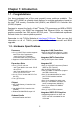
Chapter 1: Introduction 1.1 - Congratulations You have purchased one of the most powerful server solutions available. The ® Toledo q35T (S5220) is a flexible Intel platform for multiple applications, based on ® the Intel Q35 memory Controller Hub (GMCH) and 82801IR I/O Controller Hub (ICH9R) chipsets. ® Designed to support the family of Intel Socket 775 processors and 8GB of DDR2 800/667 memory, the S5220 has integrated Dual Ethernet LAN’s, an integrated graphics controller from Q35 and six SATA-II ports.
Memory BIOS • Four 240-pin DDR2 sockets support up to 8 GB • Dual channel memory bus (must be populated in pairs) • Un-buffered, non-ECC DDR2 667/800 MHz DIMM • Supports 256MB, 512MB, 1GB, 2GB DIMM • Phoenix BIOS on 8Mbit LPC Flash ROM • Supports boot from USB device • Supports ACPI 2.
Chapter 2: Board Installation You are now ready to install your motherboard. The mounting hole pattern of the Toledo q35T (S5220) matches the ATX specification. Before continuing with installation, confirm that your chassis supports an ATX motherboard. How to install our products right… the first time The first thing you should do is reading this user’s manual. It contains important information that will make configuration and setup much easier.
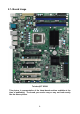
2.1- Board Image Toledo q35T S5220 This picture is representative of the latest board revision available at the time of publishing. The board you receive may or may not look exactly like the above picture.
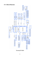
2.
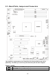
2.3 - Board Parts, Jumpers and Connectors This diagram is representative of the latest board revision available at the time of publishing. The board you receive may not look exactly like the above diagram.
Jumper/Connector Function COM2 COM2 Header CPUFAN1, FAN2/3/4/5/6 4-pin Fan Connector with Tachometer USB3/USB4/USB5/USB6 USB Front Panel Connector TYFP1 Front Panel Connector TYFP2/TYFP3 Front Panel Connector for Barebone LCM LCM Connector for Barebone J13 OPMA Connector (supports TYAN M3295) J24 Aux.
CPUFAN1 FAN5 FAN2 FAN3 J24 FAN6 FAN4 TYFP1 LCM 12
CPUFAN1/FAN2~FAN6: 4-pin Fan Connector with Tachometer Use these headers to connect the 4-pin cooling fans to your motherboard to keep the system stable and GND 1 reliable. +12V CPUFAN1: J7 FAN2: J6 Tachomet er FAN3: J53 FAN4: J47 PWM C ontrol FAN5: J51 FAN6: J48 These connectors support the tachometer monitoring and auto fan speed control. J24: Aux.
SATA1 SATA4 SATA2 SATA5 SATA3 SATA6 USB4 FP-AUDIO USB6 USB5 COM2 USB3 14
USB3/USB4/USB5/USB6: USB Front Panel Connector 2 10 1 9 Pin Signal Pin Signal 1 3 5 7 9 +5V Standby USB_AUSB_A+ GND Key Pin 2 4 6 8 10 +5V Standby USB_BUSB_B+ GND GND USB3: J25 USB4: J39 USB5: J21 USB6: J22 Use these headers to connect to the USB devices via the enclosed USB cable. COM2 (J29): COM2 Header Use these pin definitions to connect a port to COM2. *TYAN does not provide cable for this header. It is designed for barebone use only.
TYFP3 J52 J50 TYFAN TYFP2 16
TYFP2 (J28) : Front Panel Connector for Barebone It is designed for barebone use only. 11 1 12 2 Pin Signal Pin Signal 1 3 5 7 9 11 LAN1 LED+ LAN2 LED+ NC ID LED+ ID SW+ Key Pin 2 4 6 8 10 12 LAN1 LEDLAN2 LEDNC ID LEDID SWNC TYFP3 (J31) : Front Panel Connector for Barebone It is designed for barebone use only. 1 27 28 2 Pin Signal Pin Signal 1 3 5 7 HDD LED+ GND Power LED+ Warning LED+ SMBus Data Ext.
CMOS 18
CMOS (J14): Clear CMOS Jumper 1 3 Normal (Default) 1 3 Clear Use this jumper when you have forgotten your system/setup password or need to clear the system BIOS settings.
2.4 - Tips on Installing Motherboard in Chassis Before installing your motherboard, make sure your chassis has the necessary motherboard support studs installed. These studs are usually metal and are gold in color. Usually, the chassis manufacturer will pre-install the support studs. If you are unsure of stud placement, simply lay the motherboard inside the chassis and align the screw holes of the motherboard to the studs inside the case.
2.5 - Installing the Memory Before installing memory, ensure that the memory you have is compatible with the motherboard and processor. Only DDRII-800/667 DIMM modules are required. Check the TYAN Web site at: www.tyan.com for details of the type of memory recommended for your motherboard. The following diagram shows common types of DDRII memory modules. Key points to note before installing memory: For optimal dual-channel DDRII operation, always install memory in pairs beginning with DIMM1 and DIMM3.
Memory Installation Procedure Follow these instructions to install memory modules into the S5220. 1. Press the locking levers in the direction shown in the following illustration. 2. Align the memory module with the socket. The memory module is keyed to fit only one way in the socket. Key slot 3. Seat the module firmly into the socket by gently pressing down until it sits flush with the socket. The locking levers pop up into place.
2.6 - Installing the Processor and Cooling Fan Your S5220 supports the latest processor technologies from Intel. Check the TYAN website for latest processor support: http://www.tyan.com Processor Installation (LGA 775 Socket) The processor should be installed carefully. Make sure you are wearing an antistatic strap and handle the processor as little as possible. Follow these instructions to install your processor and heat sink. 1.
4. Remove the PnP cap from the load plate. PnP cap 5. Replace the load plate and return the locking lever to the locking position. 6. The CPU installation is now complete. Cooling Fan Installation After you have installed the processor, the heatsink should be installed to ensure that the processor runs efficiently and does not overheat. Use the heatsink supplied for best results. Follow these instructions to install the heatsink shown. 1. Take out the heatsink from the package.
2. Turn the board upside down and insert the heat sink spring mechanism as shown. 3. Align the heatsink with the four holes around the processor socket. 4. Press the heatsink down until the four screws are securely seated in the holes. 5. Use screw drive to secure the four screws.
2.7 - Attaching Drive Cables Attaching IDE Drive Cable Attaching the IDE drive cable is simple. These cables are “keyed” to only allow them to be connected in the correct manner. TYAN motherboards have two onboard IDE channels, each supporting two drives. The black connector designates the Primary channel, while the white connector designates the Secondary channel.
The following pictures illustrate how to connect an SATA drive 1. SATA drive cable connection 2. SATA drive power connection 3. SATA cable motherboard connector 4. SATA drive power adapter 2.8 - Installing Add-In Cards Before installing add-in cards, it’s helpful to know if they are fully compatible with your motherboard. For this reason, we’ve provided the diagrams below, showing the slots that appear on your motherboard. PCI-E x16 slot PCI-E x8 slot 32/33 PCI 2.
2.9 - Installing Optional SO-DIMM modules Your S5220 motherboard is equipped with an optional proprietary SO-DIMM connector. The 200-pin vertical SO-DIMM connector can be used for TYAN M3295 expansion card to provide such features as additional TYAN SMDC modules support. For details of available expansions cards, visit the TYAN website at http://www.tyan.com. To install a SO-DIMM expansion card: 1. Open the spring levers as shown. 2.
2.10 - Connecting External Devices The following diagram will detail the rear port stack for this S5220 motherboard: Mouse Keyboard USBx2 Serial Port VGA Port IPMI LAN USB x 2 Gigabit Ethernet x 2 Line-In Line-Out MIC NOTE: Peripheral devices can be plugged straight into any of these ports but software may be required to complete the installation. Onboard LAN LED Color Definition The two onboard Ethernet ports have green and yellow LEDs to indicate LAN status.
2.11 - Installing the Power Supply There are two power connectors on your mainboard. The board requires that you use an EPS12V power supply that has a 24-pin and an 8-pin power connector. Please be aware that ATX 2.x, ATX12V and ATXGES power supplies are not compatible with the motherboard and can damage. EPS12V (24-pin) EPS12V (8-pin) Applying power to the board 1. 2. 3. Connect the EPS 12V 8-pin power connector. Connect the EPS 12V 24-pin power connector.
Chapter 3: BIOS Setup 3.1 About the BIOS The BIOS is the basic input/output system, the firmware on the motherboard that enables your hardware to interface with your software. This chapter describes different settings for the BIOS that can be used to configure your system. The BIOS section of this manual is subject to change without notice and is provided for reference purposes only.
Getting Help Pressing [F1] displays a small help window that describes the appropriate keys to use and the possible selections for the highlighted item. To exit the Help Window, press [ESC] or the [F1] key again.
3.2 Main BIOS Setup When you enter PhoenixBIOS CMOS Setup Utility, the following screen will appear as below: Main Advanced PhoenixBIOS Setup Utility Security Power System Time: System Date: [xx:xx:xx] [xx/xx/xxxx] Legacy Diskette A: [Disabled ] X X X X X X X X Boot Exit Item Specific Help [Tab], [Shift-Tab], or [Enter] selects field. SATA Port 1 SATA Port 2 SATA Port 3 SATA Port 4 SATA Port 5 SATA Port 6 Ext. Primary Master Ext.
3.3 Main In this section, you can alter general features such as the date and time, as well as access to the IDE configuration options. Note that the options listed below are for options that can directly be changed within the Main Setup screen. Users use the arrow keys to highlight the item and then use the or keys to select the value you want in each item.
3.3.1 SATA Port 1~6/Ext. Primary Master/Slave Computer detects the hard disk drive type for each drive. Press [Enter] to view advanced details of the corresponding drive.
32 Bit I/O Enables or disables 32 bit data transfer mode. Enabling this option causes the PCI hard disk interface controller to bundle together two 16-bit chunks of data from the drive into a 32-bit group, which is then transmitted to the processor or memory. This results in a small performance increase. Options: Enabled / Disabled Transfer Mode These modes determine the speed at which data is transferred to and from the drive. The Auto option automatically determines the correct transfer rates.
3.3.2 Memory Cache This setting allows you to tweak the various cache settings for optimal performance of your system. Press [Enter] to display the various cache settings.
program writes into this memory area, it will result in a system crash. So, it is recommended that you write protect this area for optimal system performance. Options: uncached / Write Protect Cache Base 0-512K Control caching of 512K base memory. Options: uncached / Write Through / Write Protect / Write Back Cache Base 512-640K Control caching of 512K-640K base memory. Options: Write Through / Write Back Cache Extended Memory Area Control caching of system memory above one megabyte.
3.3.3 Boot Features This setting allows you to tweak the various boot settings for optimal performance of your system. Press [Enter] to display the various boot features.
QuickBoot Mode Allows the system to skip certain tests while booting. This will decrease the time needed to boot the system. Options: Disabled / Enabled Extended Memory Testing Determines the tests that will be run on extended memory (memory above 1MB) during boot up.
3.4 Advanced This section facilitates configuring advanced BIOS options for your system. Main Advanced Setup Warning PhoenixBIOS Setup Utility Security Power Boot Exit Item Specific Help Setting items on this menu to incorrect values may cause your system to malfunction. Select options for Advanced Chipset features.
3.4.1 Advanced Chipset Control This section allows you to fine tune the chipset configuration. Main PhoenixBIOS Setup Utility Advanced Security Power Advanced Chipset Control X Integrated X PCI Device Control Sub-Menu Express Sub-Menu WatchDog Mode WatchDog Timer [Disabled] [10 Mins] Memory Reclaiming [Enabled] Default Primary Video Adapter IGD – Device 2: IGD – Device 2, Function 1: DVMT 4.
Memory Reclaiming It allows you to enable or disable the system memory remap function. Options: Enabled / Disabled Default Primary Video Adapter Select [IGD] to have Internal Graphics, if supported and enabled, be used for the boot display device. Select [PEG] to have PCI Express Graphics, if supported and enabled, be used for the boot display device. To use PCI Video, select [IGD].
Native Mode Operation This feature is used to choose Native Mode for ATA. However, certain OS is not supported under Native Mode. Options: Auto / Serial ATA SATA RAID Enable When this option is enabled, the Silicon Image RAID BIOS is loaded on system start up, allowing for configuration of hardware RAID arrays. With the SATA RAID ROM option disabled, the drives attached to the controller can only act independently of one another.
3.4.1.1 Integrated Device Control Sub-Menu Main X LAN PhoenixBIOS Setup Utility Advanced Security Power Integrated Device Control Sub-Menu Control Sub-Menu Boot These items control LAN devices USB Dev #29 USB Dev #26 [Fun #0, 1, 2, 3, 7] [Fun #0, 1, 2, 7] F1 Help Esc Exit -/+ Change Values Enter Select X Sub-Menu ↑↓ Select Item ← → Select Menu Exit Item Specific Help F9 Setup Defaults F10 Save and Exit USB Dev #29 Controls Dev #29.
3.4.1.1.1 LAN Control Sub-Menu Main PhoenixBIOS Setup Utility Advanced Security Power LAN Control Sub-Menu LAN1 LAN1 Option ROM Scan: [Enabled] [Disabled] LAN2 LAN2 Option ROM Scan: [Enabled] [Disabled] F1 Help Esc Exit ↑↓ Select Item ← → Select Menu Boot Enable/Disable for the integrated LAN device. -/+ Change Values Enter Select X Sub-Menu LAN1 / LAN2 Enable/Disable for the intergrated LAN device. Options: Enabled / Disabled LAN1 / LAN2 Option ROM Scan Initialize device expansion ROM.
3.4.1.2 PCI Express Sub-Menu Main PhoenixBIOS Setup Utility Advanced Security Power PCI Express Sub-Menu PCI Express Base Address GMCH Base Address DMI Base Address Egress Port Base Address ------------------------------------------------------------------------X PCI-E1 Sub-Menu Boot Exit Item Specific Help These items are for debugging the PCI Express Graphics Port.
3.4.1.2.1 PCI-E1 Sub-Menu Main PhoenixBIOS Setup Utility Advanced Security Power PEI-E1 Sub-Menu PCI Express Graphics Port [Auto] ------------------------------------------------------------------------PEG Enabled PEG Number PEG Width -------------------------------------------------------------------------PEG Slot Number PEG Power Limit PEG Slot Card Detect F1 Help Esc Exit ↑↓ Select Item ← → Select Menu Boot Exit Item Specific Help Disabled --- Port always disabled. Enabled --- Port always enabled.
3.4.1.2.2 PCI-E2 Sub-Menu Main PhoenixBIOS Setup Utility Advanced Security Power PCI-E2 Sub-Menu PCI-E Port 1 [Auto] ------------------------------------------------------------------------Port #1 Enabled Port #1 Number Port #1 Width -------------------------------------------------------------------------Port #1 Slot Number Port #1 Power Limit Port #1 Slot Card Detect F1 Help Esc Exit ↑↓ Select Item ← → Select Menu Boot Exit Item Specific Help Disabled --- Port always disabled.
3.4.2 Advanced Processor Options This section allows you to fine-tune the processor options. Main PhoenixBIOS Setup Utility Advanced Security Power Advanced Processor Options Hyperthreading: Core Multi-Processing Single Logical Proc.
C1 Enhanced Mode This feature is used to enable the C1 Enhanced mode. Options: Enabled / Disabled PECI Interface It is used to enable/disable the Platform Environment Control Interface (PECI). Options: Disabled / Enabled Intel ® Virtualization Technology Intel Virtualization Technology is a set of platform features that support virtualization of platform hardware and multiple software environments.
3.4.3 I/O Device Configuration This setting allows you to configure I/O devices.
3.4.4 DMI Event Logging This section allows you to fine tune the DMI Event Logging configuration.
3.4.5 Hardware Monitor This section allows you to fine tune the Hardware Monitor configuration. PhoenixBIOS Setup Utility Advanced Security Power Hardware Monitor Main X Voltage Boot Exit Item Specific Help Monitoring CPU FAN1 FAN2 FAN3 FAN4 FAN5 FAN6 CPU Temp. Ambient1 Temp. Ambient2 Temp.
3.4.5.1 Voltage Monitoring Sub-Menu Main PhoenixBIOS Setup Utility Advanced Security Power Voltage Monitoring Boot Exit Item Specific Help CPU Vcore Vddr2 5V 12V 3.3V F1 Help Esc Exit ↑↓ Select Item ← → Select Menu -/+ Change Values Enter Select X Sub-Menu F9 Setup Defaults F10 Previous Values All items on this submenu can not be modified in user mode. Read only.
3.4.6 IPMI This section allows you to configure the IPMI settings. (This submenu will appear when an IPMI card is installed.
BIOS POST Watchdog Select [Disabled] if users don’t want to stop POST with any error. Options: Disabled / Enabled OS Boot Watchdog Disable or select Watchdog Timer count mode. Options: Disabled / mSecond / Second / Minute Timer for loading OS (SEC) Watch dog timer value. Options: 10 - 255 Time Out Action Select what to do when Watchdog time out. Options: No Action / System Reset 3.4.6.
3.4.6.2 System Event Log (list mode) Sub-Menu Main Advanced PhoenixBIOS Setup Utility Security Power Boot Exit System Event Log (list mode) Event ID X 0007 F1 Help Esc Exit Main [0007 Sensor Name V5VSB Date/Time Stamp Voltage 03.17.
3.4.6.3 Realtime Sensor Data Sub-Menu Main Advanced PhoenixBIOS Setup Utility Security Power Boot Exit Realtime Sensor Data Sensor Type Sensor Name Sensor Data Sensor Units Lower Limit Upper Limit LocalTemp2 H1_THERM LocalTemp1 VTIN2 H0_THERMP VTIN1 SYS_TEMP 0.00 0.00 0.00 0.00 0.00 29. 00 -127.00 degrees C degrees C degrees C degrees C degrees C degrees C degrees C 0.00 0.00 0.00 0.00 0.00 0.00 0.00 59.00 75.00 59.00 70.00 75.00 70.00 70.00 H0_DDRII_1.8Run 0.00 Volts 1.58 2.
3.4.7 Console Redirection This section allows you to configure the Console Redirection. Main PhoenixBIOS Setup Utility Advanced Security Power Console Redirection Com Port Address [Disabled] Baud Rate Console Type Flow Control Console connection: Continue C. R. after POST: [19.2K] [VT 100] [CTS/RTS] [Direct] [Off] F1 Help Esc Exit ↑↓ Select Item ← → Select Menu Boot Exit Item Specific Help If enabled, it will use a port on the motherboard.
3.5 Security These settings allow you to configure the security options for your system.
3.6 Power Use this screen to select options for the Power Settings Configuration. Main Advanced PhoenixBIOS Setup Utility Security Power ACPI Sleep Mode Resume on Time Resume Time Chassis Intrusion detect Power On By PCI After Power Failure F1 Help Esc Exit ↑↓ Select Item ← → Select Menu [S1/S3] [Off] [No] [Disabled] [Stay Off] Boot Exit Item Specific Help Select one of the ACPI power states: S1, S2, or S3. If selected, the corresponding power state will support.
3.7 Boot Use this screen to select options for the Boot Settings Configuration. Main Advanced PhoenixBIOS Setup Utility Security Power Boot Exit Item Specific Help Boot priority order Excluded from boot order F1 Help Esc Exit ↑↓ Select Item ← → Select Menu -/+ Change Values Enter Select X Sub-Menu Boot Priority Order It shows the boot priority for installed devices. Excluded from boot order It lists devices to be excluded from boot order.
3.8 Exit These settings set the exit options on your system. Main Advanced PhoenixBIOS Setup Utility Security Power Exit Saving Changes Exit Discarding Changes ↑↓ Select Item ← → Select Menu Exit Exit system Setup and save your changes to CMOS. Load Setup Defaults Discard Changes Save Changes F1 Help Esc Exit Boot Item Specific Help -/+ Change Values Enter Select X Sub-Menu Exit Saving Changes This exits BIOS setup after saving the changes made.
Chapter 4: Diagnostics Note: if you experience problems with setting up your system, always check the following things in the following order: Memory, Video, CPU By checking these items, you will most likely find out what the problem might have been when setting up your system. For more information on troubleshooting, check the TYAN website at http://www.tyan.com. 4.1 Beep Codes Fatal errors, which halt the boot process, are communicated through a series of audible beeps.
4.
Code 2Fh 30h 6Ah 6Bh 6Ch 6Eh 70h 72h 76h 7Ch 7Eh 80h 81h 82h 83h 84h 85h 86h. 87h 88h 89h 8Ah 8Bh 8Ch 8Fh 90h 91h 92h 93h Beeps / Description memory bus Enable cache before system BIOS shadow 1-4-1-1.
Code 95h Beeps / Description Install CD ROM for boot Code C9h 96h D2h 80h 81h Chipset Init Bridge Init 82h Initialize the CPU 83h 84h 85h Initialize system timer Initialize system I/O Check force recovery boot 86h 87h Checksum BIOS ROM Go to BIOS A0h 88h 8Ah 8Bh Clear huge ES segment register Fixup Multi Processor table 1-2. Search for option ROMs.
Appendix: SMDC Information Overview Tyan Server Management Daughter Card (SMDC) is a powerful yet cost-efficient solution for high-end server management hardware packages. Tyan’s goal is to provide remote system monitoring and control even when the operating system is absence or simply fails. This empowers Tyan’s server board with advanced industrial-standard features. Tyan SMDC is a snap-in card that provides essential server management solution.
Features of Tyan Server Management Monitor various system components remotely - such as fans, processor temperature, and more Remote power on and power off Console redirect -the ability to view system remotely Alert and error actions -such as audible beep, e-mail, power down and reboot SMDC runs on stand-by power -the SMDC will continue to function, even if the system is not powered on How SMDC and TSO Work The brief descriptions below will help explain how these items function.
Glossary ACPI (Advanced Configuration and Power Interface): a power management specification that allows the operating system to control the amount of power distributed to the computer’s devices. Devices not in use can be turned off, reducing unnecessary power expenditure. AGP (Accelerated Graphics Port): a PCI-based interface which was designed specifically for demands of 3D graphics applications. The 32-bit AGP channel directly links the graphics controller to the main memory.
Bus: a data pathway. The term is used especially to refer to the connection between the processor and system memory, and between the processor and PCI or ISA local buses. Bus mastering: allows peripheral devices and IDEs to access the system memory without going through the CPU (similar to DMA channels). Cache: a temporary storage area for data that will be needed often by an application. Using a cache lowers data access times, since the needed information is stored in the SRAM instead of in the slow DRAM.
IRQs, it is vital that you do not double up devices on a single line. Plug-n-Play devices will take care of this for you. Doze mode: in this mode, only the CPU’s speed is slowed. DRAM (Dynamic RAM): widely available, very affordable form of RAM which has the unfortunate tendency to lose data if it is not recharged regularly (every few milliseconds). This refresh requirement makes DRAM three to ten times slower than non-recharged RAM such as SRAM.
Enhanced IDEs (EIDEs), with maximum capacity determined by the hardware controller. I/O (Input/Output): the connection between your computer and another piece of hardware (mouse, keyboard, etc.) Initial Program Load (IPL): a feature built into BBS-compliant devices, describing those devices as capable of loading and executing an OS, as well as being able to provide control back to the BIOS if the loading attempt fails. IPL: see Initial Program Load.
PM timers (Power Management timers): software timers that count down the number of seconds or minutes until the system times out and enters sleep, suspend, or doze mode. PnP (Plug-n-Play): a design standard that has become ascendant in the industry. Plug-n-Play devices require little set-up to use. Novice end users can simply plug them into a computer that is running on a Plug-n-Play aware operating system (such as Windows 98), and go to work.
design, with cables that are simpler to route and install, smaller cable connectors, and lower voltage requirements. SDRAM (Synchronous Dynamic RAM): called as such because it can keep two sets of memory addresses open simultaneously. By transferring data alternately from one set of addresses and then the other, SDRAM cuts down on the delays associated with non-synchronous RAM, which must close one address bank before opening the next.
Technical Support If a problem arises with your system, you should first turn to your dealer for direct support. Your system has most likely been configured or designed by them and they should have the best idea of what hardware and software your system contains. Hence, they should be of the most assistance for you.
Returning Merchandise for Service During the warranty period, contact your distributor or system vendor FIRST for any product problems. This warranty only covers normal customer use and does not cover damages incurred during shipping or failure due to the alteration, misuse, abuse, or improper maintenance of products. NOTE: A receipt or copy of your invoice marked with the date of purchase is required before any warranty service can be rendered.
Notice for Canada This apparatus complies with the Class B limits for radio interference as specified in the Canadian Department of Communications Radio Interference Regulations. (Cet appareil est conforme aux norms de Classe B d’interference radio tel que specifie par le Ministere Canadien des Communications dans les reglements d’ineteference radio.) Notice for Europe (CE Mark) This product is in conformity with the Council Directive 89/336/EEC, 92/31/EEC (EMC).