TM Tiger MP S2460 User’s Manual Revision 1.03 Copyright © Tyan Computer Corporation, 2001. All rights reserved. No part of this manual may be reproduced or translated without prior written consent from Tyan Computer Corp. All registered and unregistered trademarks and company names contained in this manual are property of their respective owners including, but not limited to the following. Tyan, Tiger MP S2460 are trademarks of Tyan Computer Corporation.
Table of Contents Before you begin... .................................................................... Page 4 Chapter 1: Introduction ....................................................................... 5 1.1 1.2 1.3 1.4 Congratulations! .........................................................................................................5 Tiger MP System Block Diagram ...............................................................................6 Hardware Specifications ........................
.1 3.1-A 3.2 3.2-A 3.2-B 3.2-C 3.2-D 3.2-E 3.2-F Main Setup ...............................................................................................................33 Master and Slave Screens .......................................................................................34 Advanced Setup .......................................................................................................36 Chipset Configuration Screen .......................................................................
Before you begin... Check the box contents! The retail motherboard package should contain the following: Tiger MP motherboard 34-pin floppy cable UltraDMA-100/66/33 IDE cable Tiger MP user’s manual Tyan driver CD If any of these items are missing, please contact your vendor/dealer for replacements before continuing with the installation process. 4 http://www.tyan.
Chapter 1: Introduction 1.1 Congratulations! You are now the owner of the world’s first dual AMD processor platform! - CONSUMER EDITION! The Tyan Tiger MP™ is a direct descendent of the Thunder K7, the most critically acclaimed and decorated system board in the history of Tyan. Aimed directly at the power-user and enthusiast market, the Tiger MP is a high performance workstation platform designed for development and performance applications that require the power of dual AMD Athlon™ MP processors.
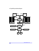
1.2 Tiger MP System Block Diagram S2K 200/ AMD Athlon MP 266MHz bus Processor 0 Socket 462 Dual-channel 200/266MHz DDR SDRAM bus 64-bit / 33MHz PCI bus AMD-762 System Controller AGP 4x bus 184-pin Registered DDR DIMMs PCI slots #1 - 5 AGP slot SMBus Winbond 83782D H/W S2K 200/ AMD Athlon MP 266MHz bus Processor 1 Socket 462 64-bit / 33MHz PCI bus AMD-766 Peripheral Bus Controller LPC bus Floppy Device Winbond W83627HF Serial Ports 6 Hardware Monitoring LPT http://www.tyan.
1.3 Hardware Specifications Processor Information Expansion Slots Chipset Information Hardware Monitoring (manufacturing option) Dual PGA462 ZIF sockets Supports dual AMD Athlon MP processors Two onboard VRMs 200MHz and 266MHz system bus support One AGP slot supports 2x/4x modes Four 64/32-bit 33MHz 5V PCI v2.2 slots Two 32-bit 33MHz 5V PCI v2.
Form Factor Regulatory ATX 12” x 10.3” (304.80mm x 261.62mm) One 20-pin power connector (requires 30A on +5V line) Stacked mouse & keyboard ports Stacked two USB ports Stacked one parallel, two serial ports FCC Class B (Declaration of Conformity) European Community CE (Declaration of Conformity) 1.4 Software Specifications OS 8 Windows NT/2000 http://www.tyan.
Chapter 2: Board Installation 2.1 Installation Once you’ve checked that everything is inside the box (see p. 4 for details), you will then be ready to install your motherboard. The mounting hole pattern of the motherboard matches the ATX board specifications, so your chassis must be capable of supporting an Extended ATX board (check the motherboard dimensions provided on p. 8). 2.2 How to install our products right.. the first time.
2.4 Quick References for Jumpers In this manual, the term “closed” and “on” are used when referring to jumpers (or jumper pins) that are active; “open” and “off” are used when referring to jumpers (or jumper pins) that are inactive. See Figure 2.0a and Figure 2.0c for examples of “on” and “off” pins and jumpers. Jumpers and pins are connected by slipping the plastic jumper connector over the top of two adjacent jumper pins (indicated by 1-2 or 2-3).
2.
2.6 Setting up Jumpers and Onboard Connectors Pinouts for certain connectors are available on the Tyan website: http://www.tyan.com 2.6-A. Front Panel Connector (J12) RST SW GND SWITCH GND SWITCH GND SWITCH 25 23 21 19 17 15 13 11 9 7 5 3 1 26 24 22 20 18 16 14 12 10 8 6 4 2 +5VCC no connect no connect SPEAKER SPEAKER PWR LED Your chassis will usually come with connectors to install onto the motherboard, such as HDD and Power LEDs. The Front Panel Connector has been implemented for such purposes.
2.6-C. CPU Front Side Bus Jumpers (J48, J49; J52, J53) (READ NOTE BELOW) With these jumpers, the CPU FSB can be set to either 200 or 266MHz. YOU MUST SET THESE JUMPERS FOR PROPER CPU OPERATION. If your CPU can only run at 200MHz, altering these FSB jumpers will not make the CPU run at 266MHz. NOTE: Tyan takes no reponsibility and will not be held liable for damage related to operation of the CPU using different settings from those of the CPU manufacturer’s specified default settings.
2.6-E. FAN Headers (P0FAN, P1FAN, FAN1, FAN2, FAN3) These headers allow for extra fans to be installed. P0FAN and P1FAN are reserved for CPU0 and CPU1 (respectively). All other fans are left to the user’s discretion. P0FAN FAN3 P1FAN FAN1 FAN2 1 ground NOTE: FAN 2 +12V 3 speed Specifications Voltage 12V Amperage 300mA The FAN connector has a 12V, 300mA limitation. Tyan takes no responsibility and will not be held liable for damage related to the misuse of any FAN header. 2.6-F.
2.6-G. SMBus Connector* (J89) This is a reserved feature for specific functions not usually required for normal board operation. J59 2.6-H. Reserved Jumper* (J34) (RESERVED) This is a reserved feature* for debugging purposes only.
2.6-I. Soft Power Connector The soft power connector is part of jumper block J12 (pins 13 and 15). This board uses the chipset for power management, including turning on and off the system. If the power button function option in the BIOS Power Management menu is set to “On/Off” (which is the default), pressing the power button once after the BIOS has booted up will turn the system on and off.
2.6-K. Flash Utility You can upgrade the BIOS of this motherboard by using the Flash Utility (see p. 44). Check the Tyan website for more details: http://www.tyan.
2.7 Mounting the Motherboard into the Chassis Your chassis may include mounting hardware. If mounting hardware was included, you can use the following examples to help you in installing your motherboard into the chassis. If your chassis has the studs integrated into the chassis wall, then you would only need to use screws (possibly included with your chassis) to install the motherboard. See the examples (Figure 2.0, shown below) for more details.
2.8 Installing Memory Please keep in mind that although some memory modules may appear to be high-quality, they may contain inferior or substandard parts. The type of memory you choose to install should be checked against the memory compatibility list, which is available from Tyan’s website at http://www.tyan.com Here are some details of memory installation for this board: At least one REGISTERED DDR DIMM* must be installed for the system to POST.
Step 3 Lock the DIMM into place by pushing the clips back on either end of the socket onto the notches in the ends of the DIMM (see pictures below for details). 1 2 Removing a DIMM Removing a DIMM is just the reverse: pull back the clips from the DIMM (see pictures below), and carefully pull the module straight out. Place the DIMMs in an anti-static bag as soon as you remove them to avoid static damage. 1 20 2 http://www.tyan.
Suggested Memory Configurations The table below shows some of the possible memory configurations. Not all possible configurations are listed. Your memory configuration may differ from one or more of the combinations** shown below.
2.9 Installing the CPU and Cooling Fan AMD Athlon MP processors up to 1.4GHz can be used on this board. For more information on CPU compatibility, check Tyan’s website at: http://www.tyan.com.
Installing the Cooling Fan(s) After a CPU has been installed, you will need to install the proper cooling device* for the CPU. This device, a heatsink/fan combination, can be purchased at many computer retail stores. Installation of the cooling device* may vary depending on the fan manufacturer’s design. You should also take space into consideration when install a cooling device*: make sure the cooling device is not too big, or else you may end up damaging components around the CPU socket.
2.10 Connecting IDE and Floppy Drives A variety of IDE and ATAPI-compliant devices can be installed on this motherboard, such as hard disk drives (HDDs) and CD-ROMs. Please keep in mind that on this motherboard, the primary IDE connector is BLACK, and the secondary IDE connector is WHITE. See the picture to the rightfor an Pin 1 example of the IDE cable properly connected to the motherboard, with the BLUE end of the IDE cable installed on the motherboard.
Connecting Floppy Drives See the picture below for an example of a floppy cable. Most of the current floppy drives on the market require that the cable be installed with the colored stripe positioned next to the power connector. In most cases, there will be a key pin on the cable which will force a proper connection of the cable. The first floppy drive (sometimes denoted as A:) is usually attached to the end of the cable with the twist in it.
2.11 Installing Add-on Cards There are a few rules you need to follow when installing add-on cards. In order to assure proper operation and a quick installation, adhere to the following guidelines: If you are going to install a PCI-bus interface card on your system, be aware that any one of the six PCI slots can support a Master or Slave device. NEVER force a card into a slot. If it won’t fit properly, look at the socket on the motherboard to make sure there are no wires or other obstructions to the slot.
2.12 Connecting PS/2, USB, and Serial Devices This motherboard includes ports for PS/2 mouse and keyboard, Universal Serial Bus (USB) devices, and serial and parallel devices. Please note that the upper PS/2 port is the mouse port, and the lower PS/2 port is for the keyboard (see Figure 2.3 below). Installation of peripheral/external devices may vary.
2.13 Connecting the power supply* This motherboard requires the following: ATX power supply, one that conforms to ATX standard 2.01 or better A minimum of 30+A on the +5V power line* The clip on the power connector should lock over the tab on the onboard connector. You shouldn’t be able to plug the power connector in any other way but just to be safe, make sure it looks like Figure 2.4b.
2.14 You are done! After double-checking the jumper settings and cable connections, and putting the case back together, you are done setting up the computer. Installing a new motherboard may seem difficult, but by following these directions, you should have a fairly uneventful time installing our products. If you do encounter problems, your vendor/dealer will be able to help you, or you can consult one of our many technical support resources (see p. 63).
2.15 Frequently Asked Questions (FAQ) Q: My system sometimes becomes unstable. How should I check the system? A: The first thing to do is to check and see if you have any device conflicts related to the IRQ, or DMA. If you are using Microsoft Windows, the Control Panel is a good place to start investigating the conflict. Please consult your operating system documentation for details. Secondly, check to make sure you are using an ATX 2.
Chapter 3: BIOS Setup Introduction to the BIOS setup The BIOS is the basic input/output system, required by the computer to perform functions such as CPU and hard drive support. This chapter describes different settings for the BIOS that can be used to configure your system. The BIOS section of the manual is subject to change without notice and is provided here for reference purposes only.
Setup Keys The table below shows how to navigate in the setup program using the keyboard. Key Function Tab Moves from one selection to the next Left/Right Arrow Keys Change from one menu to the next Up/Down Arrow Keys Move between selections Enter Opens highlighted section PgUp/PgDn Keys Change setting Getting Help Press [F1] to display a small help window that describes the appropriate keys to use and the possible selections for the highlighted item.
3.1 Main Setup In this screen, you can alter general features such as the date and time, as well as access the IDE configuration screens. Note that the options listed below are for options that can directly be changed within the Main Setup screen. FORMAT: OPTIONS: hh:mm:ss hh = hours mm = minutes ss = seconds NOTES: System time works on 24-hour format FORMAT: OPTIONS: mm/dd/yyyy mm = month dd = day yyyy = year FORMAT: OPTIONS: [size in MB] [media dimensions] 360KB, 5 1/4” 1.
3.1-A. Master and Slave screens The following options are for setting the configuration of the IDE devices installed in the system. FORMAT: OPTIONS: [option] None Auto-typing is not able to supply the drive type, or the user has selected None to disable any drives that might be installed. 1 to 39 Pre-configured drive parameters. This option is dependent on your drive. User The user must define the different parameters of the drive. Auto Auto-detect the drive parameters.
(master and slave screens, continued) FORMAT: OPTIONS: 2 sectors 4 sectors 8 sectors 16 sectors Multi-Sector Transfers All options are dependent on the drive. FORMAT: OPTIONS: [option] Disabled / Enabled Enabling LBA causes logical block addressing to be used in place of Cylinders, Heads, and Sectors. NOTES: All options are dependent on the drive. FORMAT: OPTIONS: [option] Disabled / Enabled Enables 32-bit communication between CPU and IDE card. Requires PCI or local bus.
3.2 Advanced Setup Options such as I/O device interfaces can be altered through this screen. FORMAT: OPTIONS: [option] Yes NOTES: No Does not erase ESCD. Select Yes when required to restore the manufacturer’s defaults. Reset Configuration Data Erases all configuration data in a section of memory for ESCD (Extended System Configuration Data) which stores the configuration settings for non-PnP plug-in devices.
(advanced setup, continued) Mode FORMAT: OPTIONS: [option] Normal NOTES: This option is only for Serial Port B. FORMAT: OPTIONS: [option] 3F8, 2F8 3E8, 2E8 NOTES: Recommended combinations include ‘3F8, IRQ4’ and ‘2F8, IRQ3’. FORMAT: OPTIONS: [option] IRQ4 These IRQs are paired IRQ3 with the Base I/O option. Recommended combinations include ‘3F8, IRQ4’ and ‘2F8, IRQ3’.
(advanced setup, continued) DMA Channel PCI Configuration FORMAT: OPTIONS: [option] DMA1 DMA3 These options appear when parallel port is set to ‘Enabled’. Discussed on p. 40 3.2-A. Chipset Configuration screen Options related to the graphics interface can be altered through this screen.
3.2-B. Keyboard Configuration screen Options related to the keyboard can be altered through this screen. FORMAT: OPTIONS: NumLock [option] Auto On Off FORMAT: OPTIONS: [option] 30/sec 26.7/sec 21.8/sec 18.5/sec 13.3/sec 10/sec 6/sec 2/sec FORMAT: OPTIONS: [option] 1/4 sec 1/2 sec 3/4 sec 1 sec Keyboard auto-repeat rate Keyboard auto-repeat delay ‘Auto’ will have the BIOS taking control of the NumLock key at POST. NumLock will be on after POST. NumLock will remain off after POST.
3.2-D. PCI Configuration screen Options related to the PCI slots can be altered through this screen. Primary Video FORMAT: OPTIONS: [option] AGP PCI FORMAT: OPTIONS: [option] Option ROM Scan (Enable or Disable) Enable Master (Enable or Disable) Selects primary video boot device PCI Device, Slot 1 (..2, 3, 4, 5) Latency Timer (0020h, 0040h, 0060h, 0080h, 00C0h, Default) Enables or disables device expansion ROM. Enables selected device as a PCI bus master. Not every device can function as a master.
3.3 Security Setup Security options can be altered through this screen. FORMAT: OPTIONS: [press the [ENTER] key] [Enter] Enter up to seven alphanumeric characters. You will be asked to confirm the password. In related systems, features will be accessible only by users who use the supervisor password. FORMAT: OPTIONS: [option] Disabled Enabled Set Supervisor Password Enabling requires a password on boot. Also requires prior setting of the supervisor password.
(power setup, continued) FORMAT: OPTIONS: [option] Off 1 Minute 2 Minute 4 Minute 6 Minute 8 Minute 12 Minute 16 Minute FORMAT: OPTIONS: [option] Off 5 Minutes 10 Minutes 15 Minutes 20 Minutes 30 Minutes 40 Minutes 60 Minutes FORMAT: OPTIONS: [option] On Off FORMAT: OPTIONS: [option] On Off FORMAT: OPTIONS: [00:00:00] hours minutes seconds Preset time to wake system up. FORMAT: OPTIONS: [00/00/0000] month day year Preset date to wake system up.
3.5 Boot Setup Boot settings can be altered through this screen. All options are arranged by vertical priority. FORMAT: OPTIONS: [option] (dependent on devices detected) (menu dependent on devices detected Each item detected as a removeable device, will be listed in this section. As the user presses the ‘+’ key, the item will move up in priority. The item at the top will take first priority, the second item takes next highest priority, and so on. 3.6 Exit Menu Selecting “Exit” will display this menu.
Chapter 4: System Resources Note: If you experience problems with setting up your system, always check the following things in the following order: MEMORY, VIDEO, CPU By checking these items, you will most likely find out what the problem might have been when setting up your system. For more information on troubleshooting, check the Tyan website at http://www.tyan.com 4.1 Beep Codes Fatal errors, which halt the boot process, are communicated through a series or audible beeps.
Appendix I: Glossary ACPI (Advanced Configuration and Power Interface): a power management specification that allows the operating system to control the amount of power distributed to the computer’s devices. Devices not in use can be turned off, reducing unnecessary power expenditure. AGP (Accelerated Graphics Port): a PCI-based interface which was designed specifically for demands of 3D graphics applications. The 32-bit AGP channel directly links the graphics controller to the main memory.
Bus mastering: allows peripheral devices and IDEs to access the system memory without going through the CPU (similar to DMA channels). Cache: a temporary storage area for data that will be needed often by an application. Using a cache lowers data access times, since the needed information is stored in the SRAM instead of in the slow DRAM. Note that the cache is also much smaller than your regular memory: a typical cache size is 512KB, while you may have as much as 4GB of regular memory.
DRAM (Dynamic RAM): widely available, very affordable form of RAM which has the unfortunate tendency to lose data if it is not recharged regularly (every few milliseconds). This refresh requirement makes DRAM three to ten times slower than non-recharged RAM such as SRAM. ECC (Error Correction Code or Error Checking and Correcting): allows data to be checked for errors during run-time. Errors can subsequently be corrected at the same time that they’re found.
Initial Program Load (IPL): a feature built into BBS-compliant devices, describing those devices as capable of loading and executing an OS, as well as being able to provide control back to the BIOS if the loading attempt fails. IPL: see Initial Program Load. IRQ (Interrupt Request): an electronic request that runs from a hardware device to the CPU. The interrupt controller assigns priorities to incoming requests and delivers them to the CPU.
Pipelining: improves system performance by allowing the CPU to begin executing a second instruction before the first is completed. A pipeline can be likened to an assembly line, with a given part of the pipeline repeatedly executing a set part of an operation on a series of instructions. PM timers (Power Management timers): software timers that count down the number of seconds or minutes until the system times out and enters sleep, suspend, or doze mode.
SIMM (Single In-line Memory Module): formerly the most common form of RAM for motherboards. They must be installed in pairs, and do not have the carrying capacity or the speed of DIMMs. Sleep/Suspend mode: in this mode, all devices except the CPU shut down. SRAM (Static RAM): unlike DRAM, this type of RAM does not need to be refreshed in order to prevent data loss. Thus, it is faster, and more expensive.
Technical Support If a problem arises with your system, you should turn to your dealer for help first. Your system has most likely been configured by them, and they should have the best idea of what hardware and software your system contains. Hence, they should be of the most assistance. Furthermore, if you purchased your system from a dealer near you, you can actually bring your system to them to have it serviced, instead of attempting to do so yourself (which can have expensive consequences).
Notice for the USA Compliance Information Statement (Declaration of Conformity Procedure) DoC FCC Part 15: This device complies with Part 15 of the FCC Rules. Operation is subject to the following conditions: 1) 2) this device may not cause harmful interference, and this device must accept any interference received including interference that may cause undesired operation.