Thunder n3600T /// S2937 Revision 1.00 Copyright© TYAN Computer Corporation, 2006. All rights reserved. No part of this manual may be reproduced or translated without prior written consent from TYAN Computer Corp. All registered and unregistered trademarks and company names contained in this manual are property of their respective owners including, but not limited to the following. TYAN, S2937 are trademarks of TYAN Computer Corporation.
Table of Contents Check the box contents… Chapter 1: Introduction 1.00 Congratulations! 1.01 Hardware Specifications 1.02 Software Specifications ………….………………..Page 4 …………………………..Page 5 ………….………………..Page 5 ……………….…………..Page 5 .………………………..…Page 7 Chapter 2: Board Installation 2.00 Board Image 2.01 Block Diagram 2.02 Board Parts, Jumpers and Connectors 2.03 Jumper Settings 2.04 Onboard SAS Disable Header (*JP1) 2.05 OPMA card support select Header (JP2) 2.06 Clear CMOS (JP3) 2.
Appendix: Glossary Technical Support …………………………Page 76 …………………………Page 81 3 http://www.TYAN.
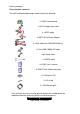
Before you begin… Check the box contents! The retail motherboard package should contain the following: 1x S2937 motherboard 1x 34-Pin floppy drive cable 6 x SATA cable 3x SATA Drive Power Adapter 4 x SAS cable (for S2937WG2NR only) 1x Ultra-DMA-100/66 IDE cable 9-pin Serial cable 1 x USB2.
Chapter 1: Instruction 1.00 – Congratulations You are now the owner of the ideal solution for rackmount servers. Tyan S2937 supports Dual AMD Opteron 2000 series processors, up to 64G Registered/ECC memories, 2 Gigabit Ethernet ports, one IDE connector, 6 Serial ATA-II (SATA) connectors, 8 SAS connectors and 2 USB ports. S2937 offers exceptional performance for your server platform needs. Remember to visit TYAN’s Website at http://www.TYAN.com.
Integrated 2D/3D PCI Graphics - ATI ES1000 controller - 32MB DDRI Frame Buffer of video memory BIOS ® - Phoenix BIOS on 8Mbit LPC Flash ROM - Support ACPI (S0, S1, S4, S5) - Serial Console Redirect - PXE via Ethernet, USB device boot - PnP, DMI 2.0, WfM 2.0 Power Management - Multiple boot options Integrated I/O Interfaces - (1) Floppy connector - (1) ATA133/100 IDE connector - (1) 9-pin Serial header - (6) SATA-II connectors - (8) SAS connectors (Four standard, One 4-in-1) - (1) USB 2.
1.02 – Software Specifications OS (Operating Systems) Support Windows XP (32/64-bit) Windows Server 2003 SP2 (32/64-bit) Windows Vista (32/64-bit) SuSE 10.0 (32/64-bit) TYAN reserves the right to add support or discontinue support any OS with or without notice. 7 http://www.TYAN.
Chapter 2: Board Installation You are now ready to install your motherboard. The mounting-hole pattern of the S2937 matches the E-ATX specifications. Before continuing with installation, confirm that your chassis supports an E-ATX motherboard. How to install our products right… the first time! The first thing you should do is to read this user’s manual. It contains important information which will make configuration and setup much easier.
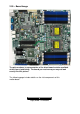
2.00 – Board Image The picture above is representative of the latest board revision available at the time of publishing. The board you receive may or may not look exactly like this picture. The following page includes details on the vital components of this motherboard. 9 http://www.TYAN.
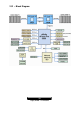
2.01 – Block Diagram 10 http://www.TYAN.
2.02 – Board Parts, Jumpers and Connectors Note: * Only for S2937WG2NR SKU. This diagram is representative of the latest board revision available at the time of publishing. The board you receive may not look exactly like the diagram above. 11 http://www.TYAN.
2.03 – Jumper settings Jumper Function Settings *JP1 Onboard SAS Disable Jumper (for S2937WG2NR only) See Section 2.04 JP2 OPMA card support select header See Section 2.05 JP3 Clear CMOS See Section 2.06 J2 USB Front Panel Header See Section 2.07 J26 Front Panel Header See Section 2.08 COM2 COM2 Header See Section 2.09 IPMB IPMB connector See Section 2.10 LAN1/ LAN2 Enable/ Disable Jumper See Section 2.11 JP11 TPM Enable/ Disable Jumper See Section 2.
Jumper Legend OPEN - Jumper OFF Without jumper cover CLOSED - Jumper ON With jumper cover To indicate the location of pin-1 To indicate the location of pin-1 JP2 JP3 JP1 J26 J2 13 http://www.TYAN.
2.04 – SAS Disable Jumper (JP1) For external disable SAS controller Installed: Disable Not installed: Enable (Default) (Default) 2.05 – OPMA card supporting select header (JP2) When using other OPMA card, remove jumper (Default) When using TYAN OPMA card, install jumper (default) 2.06 – Clear CMOS (JP3) Normal (Default) Clear Use this jumper when you have forgotten your system/setup password or need to clear the system BIOS settings.
2.08 – Front Panel Header (J26) HDD_LED+ HDD_LEDReset Button Reset Button + GND External NMI 5VSB SMBUS DATA SMBUS CLOCK JP8 2 4 6 8 10 12 14 16 18 1 3 5 7 9 11 13 15 17 PWR_LED+ PWR_LEDPWR Button + PWR Button Warn LED + Warn LED KEY GND INTRUDER# COM2 IPMB JP10 JP9 JP11 15 http://www.TYAN.
2.09 – COM2 Header (COM2) DCD 1 2 DSR RXD 3 4 RTS TXD 5 6 CTS DTR 7 8 RI GND 9 10 NA 2.10 – IPMB Connector (IPMB) Signal IPMB DATA IPMB CLK Pin 1 3 Pin 2 4 Signal GND NC 2.11 – LAN1/LAN2 Enable/ Disable Jumper (JP9, JP10) Default, Enable (Default) Install jumper to disable onboard LAN1/LAN2 2.12 – TPM Enable/ Disable Jumper (JP11) Default, Enable (Default) Install jumper to disable TPM (Trusted Platform Module) feature 16 http://www.TYAN.
2.13 – Onboard VGA Enable/ Disable Jumper (JP8) Default, Enable Install Jumper to disable onboard VGA (Default) SYS FAN3 SYS FAN7 SYS FAN1 SYS FAN5 SYS FAN4 CPU2 FAN SYS FAN2 SYS FAN6 CPU1 FAN 17 http://www.TYAN.
2.14 – CPU1 & CPU2 FAN Header (CPU FAN1, CPU FAN2) Use these headers to connect the cooling fans to the motherboard to keep the CPU stable and reliable. Pin 1 Pin 2 Pin 3 GND +12V Tachometer Pin 4 Fan PWM (speed) Control 2.15 – System FAN Headers (SYS FAN1/2/3/4/5/6/7) Use these headers to connect the cooling fans to the motherboard to keep the system stable and reliable. Pin 1 Pin 2 Pin 3 GND +12V Tachometer Note: S2937 only support 4pin FAN PWM. 18 http://www.TYAN.
JP7 J116 J118 J113 J111 J15 2.16 – TYAN Front Panel 2 for Barebones (J15) LAN2_LED+ LAN1_LED+ NC FP_ID_LED_PW IDLED_IN Reserved 2 4 6 8 10 12 1 3 5 7 9 11 LAN2_LEDLAN1_LEDNC GND GND KEY 2.17 – LCD Module Header for Barebones (J113) SIN 2 1 +5V GND 4 3 KEY SOUT 6 5 +5Vsb 19 http://www.TYAN.
2.18 – Fan Connector for Barebones (J111) CPU_FAN_TACH0 SYS_FAN_TACH1 SYS_FAN_TACH3 SYS_FAN_TACH5 NC GND GND 2 4 6 8 10 12 14 1 3 5 7 9 11 13 20 http://www.TYAN.
2.19 – Tips on Installing Motherboard in Chassis Before installing your motherboard, make sure your chassis has the necessary motherboard support studs installed. These studs are usually metal and golden. Usually, the chassis manufacturer will pre-install the support studs. If you are unsure of stud placement, simply lay the motherboard inside the chassis and align the screw holes of the motherboard to the studs inside the case.
Some chassis include plastic studs instead of metal. Although the plastic studs are usable, TYAN recommends using metal studs with screws that will fasten the motherboard more securely in place. Below is a chart detailing what the most common motherboard studs look like and how they should be installed. TIP: Use metal studs if possible, as they hold the motherboard into place more securely than plastic standoffs. 22 http://www.TYAN.
2.20 - Installing the Processor(s) Your S2937 supports the latest processor technologies from AMD. Check the TYAN website for latest processor support: http://www.tyan.com Figure 1. Detailed View of the Thermal Solution AMD PIB Platforms based on the AMD Socket F Processor 23 http://www.TYAN.
Back plate Assembly S2937 follows AMD 1U/2S CPU keep out zone spec, please use 1U RevF back plate on S2937, the distance of two mounting hole use to lock the CPU heatsink is 4.1 inch. The back plate is mounted on the backside of the motherboard and enhances local stiffness to support shock and vibration loads acting on the heat sink. The back plate assembly prevents excessive motherboard stress in the area near the processor.
4. Locate four screw holes on socket and screw the socket to the PCB board. NOTE: Do not assemble CPU before securing socket with screws. 5. Inspect Socket F assembly to PCB. The Socket F must be tightly attached onto the PCB. There must NOT be any gap between stand off the PCB.
Processor Installation The processor should be installed carefully. Make sure you are wearing an antistatic strap and handle the processor as little as possible. Follow these instructions to install your processor: 1. Place the PCB such that the socket cam side faces you. Make sure the lever hook is on your top-left side. 2. Use your left thumb and forefinger to hold the lever hook, then pull it to the left side to clear the retention tab. 3. Rotate the lever to a fully open position. 4.
6. Remove the PnP cap. Use your left hand to hold the load plate. Then use your right thumb to remove the PnP cap from the load plate. With the package in the socket, the PnP cap removal process will not damage the contacts. 7. Close the socket. Rotate the load plate onto the package lid. Engage the load lever while pressing down lightly onto the load plate. Secure the lever near the hook end under the retention tab. 8. Repeat this procedure for the second processor if necessary. 27 http://www.tyan.
2.21 – Installing the Memory Before attempting to install any memory, please make sure that the memory you have is compatible with the motherboard as well as the processor. The following diagram shows common types of DDR2 memory modules. • • All installed memory will automatically be detected and no jumpers or settings need changing. Supports up to 64GB of memory.
Memory Installation Procedure When you install the memory modules, make sure the module aligns properly with the memory slot. The modules are keyed to ensure that it is inserted only one way. The method of installing memory modules are detailed by the following diagrams. 1. Press the locking levers in the direction shown in the following illustration. 2. Align the memory module with the socket. The memory module is keyed to fit only one way in the socket. 3.
2.22 – Thermal Interface Material There are two types of thermal interface materials designed for use with the AMD Opteron processor. The most common material comes as a small pad attached to the heatsink at the time of purchase. There should be a protective cover over the material. Take care not to touch this material. Simply remove the protective cover and place the heatsink on the processor.
2.23 – Heatsink Installation Procedures Type A: CAM LEVER (TYPE) INSTALLATION 1. After placing the back plate and interface material under motherboard, place heatsink retention frame on top of motherboard. Align plastic retention bracket screw hole with CPU back-plate standoffs. Tighten screws to secure plastic retention bracket. Repeat for on other side. DO NOT OVER TIGHTEN. 2. After tightening screws secure metal clip to plastic retention bracket center tab. Repeat for on other side of heatsink. 3.
Type B: SCREW RETENTION TYPE HEATSINK 1. After placing CPU back-plate and adhesive interface material under motherboard, place heatsink retention frame on top of motherboard. Align heatsink retention frame screw hole with backplate assembly standoffs. Place heatsink inside plastic retention bracket. Place metal clip over retention frame tab. Repeat for other side. 2. Insert screw through metal clip. BE SURE METAL CLIP IS LOCKED ONTO RETENTION FRAME TAB. 3. Tighten screw through metal clip.
2.24 – Attaching Drive Cables Attaching the IDE drive cable is simple. These cables are “keyed” to only allow them to be connected in the correct manner. TYAN motherboards have two on-board IDE channels, each supporting two drives. The black connector designates the Primary channel, while the white connector designates the Secondary channel.
SATA Drivers The S2937 is also equipped with 6 Serial ATA (SATA) channels and 8 SAS connectors. Connections for these drives are also very simple. There is no need to set Master/Slave jumpers on SATA drives. Tyan has supplied six SATA cables and three SATA power adapters. If you are in need of other cables or power adapters please contact your place of purchase. The following pictures illustrate how to connect an SATA drive 1. SATA drive cable connection 2. SATA drive power connection 3.
Floppy Drives Attaching floppy diskette drives are done in a similar manner to hard drives. See the picture below for an example of a floppy cable. Most of the current floppy drives on the market require that the cable be installed with the colored stripe positioned next to the power connector. In most cases, there will be a key pin on the cable which will force a proper connection of the cable. Attach first floppy drive (drive A:) to the end of the cable with the twist in it.
2.25 – Installing Add-In Cards Before installing add-in cards, it’s helpful to know if they are fully compatible with your motherboard. For this reason, we’ve provided the diagrams below, showing the most common slots that may appear on your motherboard. Not all of the slots shown will necessarily appear on your motherboard. PCI-E x 16 slot (w/ x 4 signal) PCI-E x 16 slot (w/ x 8 signal) PCI-E x 16 slot (w/ x 8 signal) Simply find the appropriate slot for your add-in card and insert the card firmly.
2.26 – Connecting External Devices Connecting external devices to the motherboard is an easy task. The standard devices you should expect to plug into the motherboard are keyboards, mice, and printer cables. The following diagram will detail the ATX port stack for the following board. PS/2 Mouse /Keyboard OPMA Port Serial Port VGA Port GbE LAN Port x 2 USB Port x 2 Peripheral devices can be plugged straight into any of these ports bug software may be required to complete the installation.
2.27 – Installing the Power Supply There are three power connectors on your S2937. Tyan recommends that you have an EPS12V power supply which has one 24-pin, one 8-pin and one 4-pin power connectors. 24-pin PWR 8-pin PWR PWR2: 2x2 pin power Connector 4-pin PWR PWR1: 8-pin EPS 12V power connector PWR0: 24-pin power connector Applying power to the board a. Connect the EPS12V 8-pin power connector. b. Connect the EPS12V 24-pin power connector. c. Connect the EPS12V 4-pin power connector. d.
2.28 – Finishing Up Congratulations on making it this far! You’re finished setting up the hardware aspect of your computer. Before closing up your chassis, make sure that all cables and wires are connected properly, especially IDE cables and most importantly, jumpers. You may have difficulty powering on your system if the motherboard jumpers are not set correctly. In the rare circumstance that you have experienced difficulty, you can get help by asking your vendor for assistance.
Chapter 3: BIOS 3.01 About the BIOS The BIOS is the basic input/output system, the firmware on the motherboard that enables your hardware to interface with your software. This chapter describes different settings for the BIOS that can be used to configure your system. The BIOS section of this manual is subject to change without notice and is provided for reference purposes only.
Getting Help Pressing [F1] displays a small help window that describes the appropriate keys to use and the possible selections for the highlighted item. To exit the Help Window, press [ESC] or the [F1] key again.
3.02 Main BIOS Setup When you enter PhoenixBIOS CMOS Setup Utility, the following screen will appear as below: The main menu contains the following menu items: Main Use this menu for basic system configuration. Advanced Use this menu to set the Advanced Features available on your system. Security Use this menu to configure security settings for your system. Boot Use this menu to configure boot options for your system. Power Use this menu to specify your settings for power management.
3.03 Main In this section, you can alter general features such as the date and time, as well as access to the IDE configuration options. Note that the options listed below are for options that can directly be changed within the Main Setup screen. Users use the arrow keys to highlight the item and then use the or keys to select the value you want in each item. BIOS Date This shows the date that BIOS is created. Motherboard This shows Motherboard name. BIOS Version This shows the BIOS version.
System Time / System Date System Time: Adjusts the system clock. HH Hours (24hr. format): MM Minutes : SS Seconds System Date: Adjusts the system date. MM Months : DD Days : YYYY Years 44 http://www.tyan.
3.04 Advanced This section facilitates configuring advanced BIOS options for your system. Installed O/S This allows you to select the operating system installed on your system which you will use most commonly. NOTE: An incorrect setting can cause the operating system to behave unpredictably.
3.4.1 Hammer Configuration This section allows you to fine tune the hammer configuration. HT-LDT Frequency The port’s transmission frequency. Options: 1000MHz / 800MHz / 600MHz / 400MHz / 200MHz Node Interleave Interleave memory blocks across nodes. Auto will set this enabled when possible. Options: Disabled / Auto DRAM Bank Interleave Interleave memory blocks across the DRM chip selects. Auto will set this enabled when possible.
Enable the DRAM controller to designate a DIMM bank as a spare for logical swap during runtime. Options: Disabled / Enabled Auto DQS Training [Disabled]: Do DQS training on every cold boot. [Enabled]: Train DQS only when the installed DIMMs are changed. Options: Disabled / Enabled Processor Assisted Virtualizations It allows you to enable the hardware virtualization support. Options: Disabled / Enabled Multiprocessor Specification It allows you to configure the MP specification revision level.
Set the level of ECC protection. If User is selected, individual ECC options may be changed. Other options besides Disabled serve as presets. For super mode, all of memory is scrubbed every 8 hours. Options: Disabled / Basic / Good / Super / Max User ECC Error Checking Enable the DRAM controller to read/write ECC check-bits on the DIMMs and it allows the north bridge to check and correct ECC errors on the DRAM bus during normal CPU or bus master read requests.
3.4.1.2 Memory Controller Options Sub-Menu Mem Hole Remap Recover DRAM lost to PCI address space below 4GB. Options: Disabled / Enabled CAUTION: 1. If enabled, Bank and Node Interleaving, Dram ECC Scrubbing are disabled. 2. Actual Hole size may be larger than selected, depending on Dram bank population. IOMMU IOMMU is supported on Linux based systems to convert 32bit PCI IO addresses to 64bits. Options: Disabled / Enabled IOMMU Size It allows you to select the IOMMU size.
3.4.1.3 Memory Config Options Sub-Menu Mem Clock Mode Options: Auto / Limit Memory Clock Options: DDR2 400 / DDR2 500 / DDR2 667 / DDR2 800 50 http://www.tyan.
3.4.2 Integrated Devices This section allows you to configure Integrated Devices. USB Control Enable/disable USB controllers. Options: Disabled / USB1.1 + USB2 USB BIOS Legacy Support Enables or disables support for USB keyboards or mice. (Enable for use with a non-USB aware Operating System such as DOS or UNIX) Options: Disabled / Enabled SATA0 / SATA1 / SATA2 Controller Enable/disable First Serial ATA Device. NOTE: Mobile platform, enable SATA, SAVE and EXIT BIOS SETUP.
3.4.2.1 NV RAID Configuration Sub-Menu NV RAID Configuration Enable/disable NVIDIA RAID control. SATA controller must be enabled for RAID feature to function. Enabling Master SATA0 Secondary requires enabling Secondary SATA Channel. Both options are listed in Integrated Devices. Options: Disabled / Enabled SATA port 0/1/2/3/4/5 Raid Enable this device as RAID.
3.4.3 IDE Configuration This section allows you to fine tune the IDE configuration. Large Disk Access Mode UNIX, Novell Netware or other operating systems, select [Other]. If you are installing new software and the drive fails, change this selection and try again. Different operating systems require different representations of drive geometries. Options: Other / DOS Local Bus IDE Adapter Enable the integrated local bus IDE adapter.
3.4.3.1 Primary Master / Slave Sub-Menu The system displays advanced details like the number of heads/cylinders/sectors on the detected disk and the maximum storage capacity of the disk. This option lets you set the following hard disk parameters: Type Selects the type of device connected to the system. Options: None / ATAPI Removable / CD-ROM / IDE Removable / Other ATAPI / User / Auto Multi-Sector Transfers This option allows you to specify the number of sectors per block for multiple sector transfers.
When LBA is turned on, the BIOS will enable geometry translation. This translation may be done in the same way that it is done in Extended CHS or large mode, or it may be done using a different algorithm called LBA-assist translation. The translated geometry is still what is presented to the operating system for use in Int 13h calls. The difference between LBA and ECHS is that when using ECHS the BIOS translates the parameters used by these calls from the translated geometry to the drive's logical geometry.
3.4.4 Floppy Configuration This section allows you to select the Floppy Configuration. Legacy Diskette A Selects floppy type. Options: Disabled / 360 KB, 5.25 in / 1.2 MB, 5.25 in / 720 KB, 3.5 in / 1.44/1.25 MB, 3.5 in / 2.88 MB, 3.5 in Floppy check Options: Disabled / [Enabled] 56 http://www.tyan.
3.4.5 I/O Device Configuration This setting allows you to select the I/O Device Configuration. Serial Port A Configure Serial Port A using options: [Disabled]: no configuration [Enabled]: user configuration [Auto]: BIOS or OS chooses configuration [OS Controlled]: displayed when controlled by OS • Options: Disabled / Enabled / Auto Base I/O Address Set the base I/O address for Serial Port A. • Options: 3F8 / 2F8 / 3E8 / 2E8 Interrupt Set the Interrupt for Serial Port A.
Mode: Options: Normal / IR / ASK-IR Base I/O Address Set the base I/O address for serial port B. Options: 3F8 / 2F8 / 3E8 / 2E8 Interrupt Set the interrupt for serial port B. Options: IRQ3 / IRQ4 Parallel Port Configure parallel port using options: [Disabled]: No configuration [Enabled]: User configuration Options: Disabled / Enabled / Auto Base I/O Address Set the base I/O address for the parallel port. Options: 378 / 278 / 3BC Interrupt Set the interrupt for the parallel port.
3.4.6 Hardware Monitor / IPMI This setting allows you to view the onboard hardware monitor device. IPMI If OPMA is Found: IPMI else : Hardware Monitor AutoFan Mode [Quiet Fans] are working with the lowest possible speed [Auto Mode] Optimum temperature Control at Maximum CPU performance [Full Speed] All Fans are working Options: Quiet / Auto / Full Speed 59 http://www.tyan.
3.4.7 Console Redirection This setting allows you to configure Console Redirection. COM Port Address If enabled, it will use a port on the motherboard. Options: Disabled / On-board COM A / On-board COM B Baud Rate Enables the specified baud rate. Options: 300 / 1200 / 2400 / 9600 / 19.2K / 38.4K / 57.6K / 115.2K Console Type Enables the specified console type. Options: VT100 / VT100, 8bit / PC-ANSI / VT100+ / VT-UTF8 / ASCII Flow Control Enables flow control.
3.4.8 DMI Event Logging This setting allows you to configure DMI Event Logging. Event Log Capacity It reports the space available in the DMI event log. If set to [Full], the event log has no more available space to store DMI events. (read only) Event Log Validity It reports the validity of the DMI event log. (read only) View DMI Event Log It allows you to view the contents of the DMI event log. (read only) Clear All DMI Event Logs Setting this to [Yes] will clear the DMI event log after rebooting.
3.05 Security These settings allow you to configure the security options for your system. Supervisor Password Is / User Password Is The system displays the current supervisor and user passwords. Set Supervisor / User Password This option allows the supervisor / user to set their password to restrict access to the BIOS settings. Password on boot When enabled, the system will ask for a password at every boot. The system will continue booting only if the correct password is entered.
3.06 Boot Use this screen to configure the boot priority order. Halt on Errors [ALL Errors] Halt POST on any errors. [No Halt] No halt on any errors. Options: No Halt / All Errors QuickBoot Mode This allows the system to skip certain tests while booting. This will decrease the time needed to boot the system. Options: Enabled / Disabled QuietBoot Mode This displays the diagnostic screen during boot.
This allows you to select the primary display device. Options: OnBoard VGA / PEG1(PCI-E Slot1 4x) / PEG2(PCI-E Slot2 8x) /PEG3(PCI-E Slot3 8x) EndLess PXE Loop If enabled, system will only trying to boot up from PXE, if PXE boot is failed, system will keep on trying until reaching PXE server. Options: Enabled / Disabled 3.6.1 Boot Device Priority Boot Priority Order It shows the boot priority for installed devices. Excluded from boot order It lists devices to be excluded from boot order. 64 http://www.
3.07 Power These settings allow you to control the Power Configuration. Enable ACPI This allows you to enable or disable ACPI BIOS (Advance Configuration and Power Interface). Options: No / Yes Power Button Off [Enabled] will let power button possible to shutdown the system in legacy OS without holding for 4 seconds. [Disabled] will force 4-second power button to shutdown the system. Options: Enabled / Disabled After Power Failure Sets the mode of operation if an AC/Power Loss occurs.
3.7.1 Spread Spectrum TGIO Spread Spectrum Disable or Enable TGIO Spread Spectrum Options: Disabled / Down Spread LDT Spread Spectrum Disable or Enable LDT Spread Spectrum Options: Disabled / Center Spread / Down Spread SATA Spread Spectrum Disable or Enable LDT Spread Spectrum Options: Disabled / Enabled CPU PLL Spread Spectrum Disable or Enable CPU PLL Spread Spectrum Options: Disabled / Center Spread / Down Spread 66 http://www.tyan.
3.7.2 ACPI Table High Precision Event timer Enable/Disable Multimedia Timer support. Options: No / Yes ACPIMCFG Table Some version of Linux 'Kernel has problem of scan build-in memory controller or PCI BUS not covered by MCFG table, then we should disable ACPI MCFG tables. Options: Enabled / Disabled AMD PowerNow! AMD PowerNow! Technology with Optimized Power Management (OPM).' Options: Disabled / Enabled ACPI SRAT Table Enable ACPI 2.0 static resources affinity table for ccNUMA systems.
3.08 Exit These settings set the exit options on your system. Exit Saving Changes This exits BIOS setup after saving the changes made. Exit Discarding Changes This exits BIOS setup after discarding the changes made. Load Setup Defaults This loads the factory default values. Discard Changes This discards all changes made without exiting BIOS setup. Save Changes This saves all changes made without exiting BIOS setup. 68 http://www.tyan.
NOTE 69 http://www.tyan.
Chapter 4: Diagnostics Note: if you experience problems with setting up your system, always check the following things in the following order: Memory, Video, CPU By checking these items, you will most likely find out what the problem might have been when setting up your system. For more information on troubleshooting, check the TYAN website at: http://www.tyan.com. 4.1 Flash Utility Every BIOS file is unique for the motherboard it was designed for.
4.
Code 6Ah 6Bh 6Ch 6Eh 70h 72h 76h 7Ch 7Eh 80h 81h 82h 83h 84h 85h 86h.
E9h EAh EBh Initialize Multi Processor Initialize OEM special code Initialize PIC and DMA F1h F2h F3h ECh EDh EEh EFh F0h Initialize Memory type Initialize Memory size Shadow Boot Block System memory test Initialize interrupt vectors F4h F5h F6h F7h 73 http://www.tyan.
Appendix I: How to Make a Driver Diskette Follow the steps below to make a driver diskette from the TYAN driver CD provided. 1. Start the system and insert the TYAN CD into the CD-ROM drive to boot from CD. You will see the following menu. Then press [1] and [Enter] to boot the system to TYAN diskette maker. (If you would like to boot from hard disk, press 0 and Enter or just wait for 10 seconds to boot automatically from hard disk.). Boot from CD: ISOLINUX 2.00 2002-10-25 Copyright (C) 1994-2002 H.
** nVidia** ====Choose Chipset Model==== 01 nVidia NVRAID EXIT 4. After selecting the chipset model, select the OS to start the diskette making. TYAN Driver Diskette Maker ====nVidia NVRAID SATA and RAID Driver==== Diskette Diskette Diskette Diskette =01= =02= =03= =04= Microsoft Windows 2000 32-bit Microsoft Windows XP 32-bit Microsoft Windows XP 64bit Microsoft Windows 2003 64-bit Back 5. Follow the instruction on menu to insert a diskette and press [ENTER].
Glossary ACPI (Advanced Configuration and Power Interface): a power management specification that allows the operating system to control the amount of power distributed to the computer’s devices. Devices not in use can be turned off, reducing unnecessary power expenditure. AGP (Accelerated Graphics Port): a PCI-based interface which was designed specifically for demands of 3D graphics applications. The 32-bit AGP channel directly links the graphics controller to the main memory.
Cache: a temporary storage area for data that will be needed often by an application. Using a cache lowers data access times since the information is stored in SRAM instead of slower DRAM. Note that the cache is also much smaller than your regular memory: a typical cache size is 512KB, while you may have as much as 4GB of regular memory. Closed and open jumpers: jumpers and jumper pins are active when they are “on” or “closed”, and inactive when they are “off” or “open”.
Firmware: low-level software that controls the system hardware. Form factor: an industry term for the size, shape, power supply type, and external connector type of the Personal Computer Board (PCB) or motherboard. The standard form factors are the AT and ATX. Global timer: onboard hardware timer, such as the Real-Time Clock (RTC). HDD: stands for Hard Disk Drive, a type of fixed drive. H-SYNC: controls the horizontal synchronization/properties of the monitor.
PCI PIO (PCI Programmable Input/Output) modes: the data transfer modes used by IDE drives. These modes use the CPU for data transfer (in contrast, DMA channels do not). PCI refers to the type of bus used by these modes to communicate with the CPU. PCI-to-PCI bridge: allows you to connect multiple PCI devices onto one PCI slot. Pipeline burst SRAM: a fast secondary cache. It is used as a secondary cache because SRAM is slower than SDRAM, but usually larger.
bus or a set of SCSI busses. SISL: SCSI Interrupt Steering Logic ( LSI ) (only on LSI SCSI boards) Sleep/Suspend mode: in this mode, all devices except the CPU shut down. SDRAM (Static RAM): unlike DRAM, this type of RAM does not need to be refreshed in order to prevent data loss. Thus, it is faster and more expensive. Standby mode: in this mode, the video and hard drives shut down; all other devices continue to operate normally. UltraDMA-33/66/100: a fast version of the old DMA channel.
Technical Support If a problem arises with your system, you should turn to your dealer for help first. Your system has most likely been configured by them, and they should have the best idea of what hardware and software your system contains. Furthermore, if you purchased your system from a dealer near you, you can bring your system to them to have it serviced instead of attempting to do so yourself (which can have expensive consequences).
service by calling the manufacturer for a Return Merchandise Authorization (RMA) number. The RMA number should be prominently displayed on the outside of the shipping carton and the package should be mailed prepaid. TYAN will pay to have the board shipped back to you.