Thunder n3600R /// S2912 Version 1.0 Copyright Copyright © TYAN Computer Corporation, 2006. All rights reserved. No part of this manual may be reproduced or translated without prior written consent from TYAN Computer Corp. Trademark All registered and unregistered trademarks and company names contained in this manual are property of their respective owners including, but not limited to the following. TYAN, Taro and Thunder n3600R are trademarks of TYAN Computer Corporation.
Table of Contents Chapter 1: Introduction 1.1 Congratulations 1.2 Hardware Specifications Chapter 2: Board Installation 2.1 Board Image 2.2 Block Diagram 2.3 Board Parts, Jumpers and Connectors 2.4 Tips on Installing Motherboard in Chassis 2.5 Installing the Processor(s) 2.6 Installing the Memory 2.7 Attaching Drive Cables 2.8 Installing Add-In Cards 2.9 Connecting External Devices 2.10 Installing the Power Supply 2.11 Finishing Up Chapter 3: BIOS 3.1 About the BIOS 3.2 Main BIOS Setup 3.3 Main Menu 3.
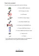
Check the box contents! The retail motherboard package should contain the following: 1x Thunder n3600R motherboard 1x 34-Pin floppy drive cable 6 x SATA cable 3 x SATA Drive Power Adapter 1 x Ultra-DMA-100/66 IDE cable 2 x SAS cable (for S2912WG2NR only) 1 x Thunder n3600R User’s Manual 1 x Thunder n3600R Quick Reference Guide 1 x TYAN driver CD 1 x I/O shield If any of these items are missing, please contact your vendor/dealer for replacement before continuing with the installation process.
NOTE 4 http://www.tyan.
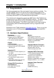
Chapter 1: Introduction 1.1 - Congratulations You have purchased one of the most powerful server solutions available. The Thunder n3600R (S2912) is a high-end server motherboard, based on the NVIDIA NPF3600 chipset. It also includes the Winbond W83627HF Super IO and Analog Devices ADT7476 Hardware Monitoring chipsets. This motherboard is designed to support two AMD Opteron RevF 2000 Series processors and up to 32GB of DDR2 400/533/667 memory.
• Supporting RAID 0 (Integrated Stripping), RAID 1E (Integrated Enchanced Mirroring) and RAID 1 (Integrated Mirroring) System Management • CPU thermal & voltage monitor support • Six 4-pin fan header (PWM and tachometer support) • One 2-pin chassis intrusion header • Watchdog timer support Expansion Slots • Two PCI Express x 16 slots - one with x16 signal - one with x8 signal • One HTX-pro connector - supports Pathscale InfiniPath HTX Adapter • One OPMA connector for KVM BIOS • Phoenix BIOS on 8Mbit LPC
Chapter 2: Board Installation Precautions: The Thunder n3600R supports SSI, EPS12V type power supplies (24pin + 8pin +4pin) and will not operate with any other types. For proper power supply installation procedures see page 32. DO NOT USE ATX 2.x or ATXGES power supplies as they will damage the board and void your warranty. How to install our products right… the first time The first thing you should do is reading this user’s manual.
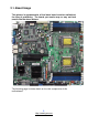
2.1- Board Image This picture is representative of the latest board revision available at the time of publishing. The board you receive may or may not look exactly like the above picture. The following page includes details on the vital components of this motherboard. 8 http://www.tyan.
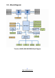
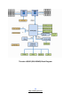
2.2 - Block Diagram Thunder n3600R (S2912WG2NR) Block Diagram 9 http://www.tyan.
Thunder n3600R (S2912G2NR) Block Diagram 10 http://www.tyan.
2.3 - Board Parts, Jumpers and Connectors This diagram is representative of the latest board revision available at the time of publishing. The board you receive may not look exactly like the above diagram. Jumper Legend OPEN - Jumper OFF, without jumper covered CLOSED – Jumper ON, with jumper covered 11 http://www.tyan.
Jumper/Connector Function CPU_FAN1/CPU_FAN2 CPU FAN Connector SYSFAN1/2/3/4/5/6/7 FAN Connector IPMB (J14) IPMB Connector COM2 (J95) COM2 Header FRNTUSB0_1 (J2) FRNTUSB2_3 (J3) FRNTUSB4_5 (J4) USB Pin Header J26 (TYFP) Front Panel Header J113 LCD Model Pin Header JP1* SAS Disable Jumper (for S2912WG2NR JP2 OPMA Card Select Jumper JP3 Clear CMOS Jumper J15/J111 Reserved for Barebone only) 12 http://www.tyan.
SYSFAN7 SYSFAN3 SYSFAN5 SYSFAN4 CPU_FAN2 SYSFAN1 SYSFAN6 SYSFAN2 CPU_FAN1 13 http://www.tyan.
CPU_FAN1/2 and SYSFAN1/2/3/4: 4-pin Fan Connector with Speed Control Use these headers to connect the cooling fans to the motherboard to keep the system stable and reliable. GND 1 This connector supports the tachometer monitoring +1 2V Tac ho me ter and auto fan speed control. PWM Pin 1 GND Pin 2 +12V Pin 3 Tachometer Pin 4 PWM SYSFAN5/6: 3-pin Fan Connector Use these headers to connect the cooling fans to the motherboard to keep the system stable and reliable.
IPMB (J14) FRNTUSB4_5 (J4) J26 (TYFP) FRNTUSB0_1 (J2) 15 http://www.tyan.
IPMB (J14): IPMB Connector 1 Pin 1 IPMB DATA IPMB CLK Pin 3 Pin 2 GND Pin 4 NC J2/J3/J4: USB Front Panel Header 2 J2/J4 1 9 10 Use this header to connect to front panel USB connector. 10 9 J3 1 2 Signal Pin Pin VCC 1 2 Signal VCC DATA- 3 4 DATA- DATA+ 5 6 DATA+ GND 7 8 GND KEY 9 10 NA J26 (TYFP): Front Panel Header Reset SW- Reset SW+ HDD LED- HDD LED+ 11 9 7 5 3 1 18 16 14 12 10 8 6 4 2 PWR SW+ Power LED- Power LED+ 16 http://www.tyan.
COM2 (J95) J113 J15 17 http://www.tyan.
COM2 (J95): COM2 Header Use these pin definitions to connect a port to COM2. *TYAN does not provide cable for this header. It is designed for OEM use only.
JP2 JP3 JP1 J111 19 http://www.tyan.
J111: Fan Connector for Barebone (reserved) 2 14 1 13 Pin Signal Pin Signal 1 3 5 7 9 11 13 CPUFAN0_TACH CPUFAN1_TACH SYSFAN0_TACH SYSFAN1_TACH NC GND GND 2 4 6 8 10 12 14 CPUFAN2_TACH CPUFAN3_TACH CPU_FAN_TACH2 SYSFAN5_TACH NC KEY CPUFAN0_PWM JP1: SAS Disable Jumper (for S2912WG2NR only) 1 Open: Enable SAS Controller (Default) 1 Closed: Disable SAS Controller JP2: OPMA Card Supporting Select Jumper 1 Open: Use other OPMA card 1 Closed: Use TYAN OPMA card (Default) JP3: Clear CMOS Jumpe
2.4 - Tips on Installing Motherboard in Chassis Before installing your motherboard, make sure your chassis has the necessary motherboard support studs installed. These studs are usually metal and are gold in color. Usually, the chassis manufacturer will pre-install the support studs. If you are unsure of stud placement, simply lay the motherboard inside the chassis and align the screw holes of the motherboard to the studs inside the case.
2.5 - Installing the Processor(s) Your S2912 supports the latest processor technologies from AMD. Check the TYAN website for latest processor support: http://www.tyan.com Figure 1. Detailed View of the Thermal Solution AMD PIB Platforms based on the AMD Socket F Processor 22 http://www.tyan.
Back plate Assembly S2912 follows AMD 1U/2S CPU keep out zoon spec, please use 1U RevF back plate on S2912, the distance of two mounting hole use to lock the CPU heatsink is 4.1 inch. The back plate is mounted on the backside of the motherboard and enhances local stiffness to support shock and vibration loads acting on the heat sink. The back plate assembly prevents excessive motherboard stress in the area near the processor.
4. Locate four screw holes on socket and screw the socket to the PCB board. NOTE: Do not assemble CPU before securing socket with screws. 5. Inspect Socket F assembly to PCB. The Socket F must be tightly attached onto the PCB. There must NOT be any gap between stand off the PCB. 24 http://www.tyan.
2.6 - Installing the Memory Before installing memory, ensure that the memory you have is compatible with the motherboard and processor. Only DDR2-400/533/667 DIMM modules are required. Check the TYAN Web site at: www.tyan.com for details of the type of memory recommended for your motherboard. The following diagram shows common types of DDR2 memory modules. Key points to note before installing memory: • • Only DDR2 400/533 /667 Registered ECC memory modules are supported.
Memory Installation Procedure Follow these instructions to install memory modules into the S2912. 1. Press the locking levers in the direction shown in the following illustration. 2. Align the memory module with the socket. The memory module is keyed to fit only one way in the socket. Key slot 3. Seat the module firmly into the socket by gently pressing down until it sits flush with the socket. The locking levers pop up into place. 26 http://www.tyan.
Key points to note before installing memory into Thunder n3600R: For optimal dual-channel DDR2 operation, always install memory in pairs beginning with outer most dimm slots CPU1 DIMMA2 and CPU1_ DIMMB2. Memory modules of the same type and density are required for dual-channel DDR2 operation. Mismatched memory may cause system instability. Refer to the following table for supported DDR2 populations.
2.7 - Attaching Drive Cables Attaching IDE Drive Cable Attaching the IDE drive cable is simple. The cable is “keyed” to only allow it to be connected in the correct manner. Attaching IDE cable to the IDE connector is illustrated below: Simply plug in the BLUE END of the IDE cable into the motherboard IDE connector, and the other end into the drive. Each standard IDE cable has three connectors, two of which are closer together.
The following pictures illustrate how to connect an SATA drive 1.SATA drive cable connection 2. SATA drive power connection 3. SATA cable motherboard connector 4. SATA drive power adapter Attaching Floppy Drive Cables Attaching floppy diskette drives are done in a similar manner to hard drives. See the picture below for an example of a floppy cable. Most of the current floppy drives on the market require that the cable be installed with the colored stripe positioned next to the power connector.
2.8 - Installing Add-In Cards Before installing add-in cards, it’s helpful to know if they are fully compatible with your motherboard. For this reason, we’ve provided the diagrams below, showing the most common slots that may appear on your motherboard. Not all of the slots shown will necessarily appear on your motherboard.
2.9 - Connecting External Devices Your motherboard supports a number of different interfaces for connecting peripherals. Some I/O ports may not be available with the board due to the different configurations. PS/2 Mouse/Keyboard Serial Port VGA Port LAN2 LAN1 RJ-45 for OPMA USB x 2 Peripheral devices can be plugged straight into any of these ports but software may be required to complete the installation.
2.10- Installing the Power Supply There are three power connectors on your Thunder n3600R. The Thunder n3600R requires an EPS12V (24 pin + 8 pin +4 pin) power supply. All the three power connectors must be installed in order to boot up the system. Please be aware that ATX 2.x and ATXGES power supplies are not compatible with the board and can damage the motherboard and/or CPU(s). 1 12 13 24 1 4 5 8 3 4 1 2 12 11 10 9 8 7 6 5 4 3 2 1 +3.3V +12V1 +12V1 +5VSB PWR OK GND +5V GND +5V GND +3.3V +3.
2.11 – Finishing Up Congratulations! You’re finished setting up the hardware aspect of your computer. Before closing up your chassis, make sure that all cables and wires are connected properly, especially IDE cables and jumpers. You may have difficulty powering on your system if the motherboard jumpers are not set correctly. In the rare circumstance that you have experienced difficulty, you can find help by asking your vendor for assistance.
Chapter 3: BIOS 3.1 About the BIOS The BIOS is the basic input/output system, the firmware on the motherboard that enables your hardware to interface with your software. This chapter describes different settings for the BIOS that can be used to configure your system. The BIOS section of this manual is subject to change without notice and is provided for reference purposes only.
Getting Help Pressing [F1] displays a small help window that describes the appropriate keys to use and the possible selections for the highlighted item. To exit the Help Window, press [ESC] or the [F1] key again.
3.2 Main BIOS Setup When you enter PhoenixBIOS CMOS Setup Utility, the following screen will appear as below: The main menu contains the following menu items: Main Use this menu for basic system configuration. Advanced Use this menu to set the Advanced Features available on your system. Security Use this menu to configure security settings for your system. Boot Use this menu to configure boot options for your system. Power Use this menu to specify your settings for power management.
3.3 Main In this section, you can alter general features such as the date and time, as well as access to the IDE configuration options. Note that the options listed below are for options that can directly be changed within the Main Setup screen. Users use the arrow keys to highlight the item and then use the or keys to select the value you want in each item. BIOS Date This shows the date that BIOS is created. BIOS Version This shows the BIOS version.
Extended Memory This displays the amount of extended memory present on the system. Cache Ram This displays the amount of cache memory present on the system. System Time / System Date System Time: Adjusts the system clock. HHHours (24hr. format): MMMinutes : SSSeconds System Date: Adjusts the system date. MMMonths : DDDays : YYYYYears 38 http://www.tyan.
3.4 Advanced This section facilitates configuring advanced BIOS options for your system. Installed O/S This allows you to select the operating system installed on your system which you will use most commonly. NOTE: An incorrect setting can cause the operating system to behave unpredictably.
3.4.1 Hammer Configuration This section allows you to fine tune the hammer configuration. HT-LDT Frequency The port’s transmission frequency. Options: 1000MHz / 800MHz / 600MHz / 400MHz / 200MHz Node Interleave Interleave memory blocks across nodes. Auto will set this enabled when possible. Options: Disabled / Auto DRAM Bank Interleave Interleave memory blocks across the DRM chip selects. Auto will set this enabled when possible.
Auto DQS Training [Disabled]: Do DQS training on every cold boot. [Enabled]: Train DQS only when the installed DIMMs are changed. Options: Enabled / Disabled Multiprocessor Specification It allows you to configure the MP specification revision level. systems will require 1.1 for compatibility reasons. Options: 1.4 / 1.1 Some operating 3.4.1.1 ECC Options Sub-Menu ECC Mode Set the level of ECC protection. If User is selected, individual ECC options may be changed.
Options: Disabled / Enabled L2 ECC Scrub Control Sets the rate of background scrubbing for the L2 cache. Options: Disabled / Enabled ECC Error Log Enable the MCA to log or report ECC errors on the DRAM bus. NOTE: The MCA must still be programmed according to the desired MCE outcome. Options: Disabled / Enabled DRAM ECC Scrub Control Sets the rate of background scrubbing for DRAM.
1. If enabled, Bank and Node Interleaving, Dram ECC Scrubbing are disabled. 2. Actual Hole size may be larger than selected, depending on Dram bank population. IOMMU IOMMU is supported on Linux based systems to convert 32bit PCI IO addresses to 64bits. Options: Disabled / Enabled IOMMU Size It allows you to select the IOMMU size. Options: 32 MB / 64 MB / 128 MB / 256 MB / 512 MB / 1 GB / 2 GB 43 http://www.tyan.
3.4.2 Integrated Devices This section allows you to configure Integrated Devices. USB Control Enable/disable USB controllers. Options: Enabled / Disabled USB BIOS Legacy Support Enables or disables support for USB keyboards or mice. (Enable for use with a non-USB aware Operating System such as DOS or UNIX) Options: Disabled / Enabled Self-Healing Enable/disable USB Self-Healing feature. Options: Disabled / Enabled MAC1 LAN Enable/disable MAC1 LAN device.
MAC2 LAN Bridge Enable MAC2 LAN Bridge. Options: Enabled / Disabled MAC Address Read only. Azalia Codec Enable/disable Azalia audio interface. Options: Enabled / Disabled SATA0 / SATA1 / SATA2 Controller Enable/disable First Serial ATA Device. NOTE: Mobile platform, enable SATA, SAVE and EXIT BIOS SETUP. Then must do a power cycle during next POST. Options: Enabled / Disabled Interrupt Mode Select interrupt mode between 8259/PIC mode or APIC mode. Options: APIC / PIC 45 http://www.tyan.
3.4.2.1 NV RAID Configuration Sub-Menu NV RAID Configuration Enable/disable NVIDIA RAID control. SATA controller must be enabled for RAID feature to function. Enabling Master SATA0 Secondary requires enabling Secondary SATA Channel. Both options are listed in Integrated Devices. Options: Disabled / Enabled Master SATA 0/1/2 Primary & Master SATA 0/1/2 Secondary Enable this device as RAID. Options: Disabled / Enabled 46 http://www.tyan.
3.4.3 FirstWare Configuration This section allows you to fine tune the FirstWare Configuration. FirstWare Language Sets the current FirstWare language to the selected language. Options: English / Spanish / French / German / Italian / Japanese / Chinese (S) / Korean / Chinese (T) FirstWare authentication Level Selects FirstWare authentication level. Options: High / Medium / Low FirstWare Video Mode Selects FirstWare Video Mode. Options: 640 x 480 / 800 x 600 / 1024 x 768 / 1280 x 1024 47 http://www.tyan.
3.4.4 PCI Configuration Available OPROM Space This shows the available OPROM space Press [Enter] to enter each sub-menu for configuration. 3.4.4.1 Integrated SAS Controller Sub-Menu Integrated SAS Enable the integrated SAS controller. Options: Disabled / Enabled 48 http://www.tyan.
3.4.4.2 PCI/PNP ISA UMB Region Exclusion Sub-Menu C800-CBFF / CC00-CFFF / D000-D3FF/ D400-D7FF / D800-DBFF / DC00-DFFF Reserves the specified block of upper memory for use by legacy ISA devices. Options: Reserved / Available 3.4.4.3 PCI/PNP ISA IRQ Resource Exclusion Sub-Menu IRQ 3/4/5/7/9/10/11/15 Reserves the specified IRQ for use by legacy ISA devices. Options: Reserved / Available 49 http://www.tyan.
3.4.5 IDE Configuration This section allows you to fine tune the IDE configuration. Large Disk Access Mode UNIX, Novell Netware or other operating systems, select [Other]. If you are installing new software and the drive fails, change this selection and try again. Different operating systems require different representations of drive geometries. Options: Other / DOS Local Bus IDE Adapter Enable the integrated local bus IDE adapter. Options: Primary / Secondary 50 http://www.tyan.
3.4.5.1 Primary Master/Slave Sub-Menu The system displays advanced details like the number of heads/cylinders/sectors on the detected disk and the maximum storage capacity of the disk. This option lets you set the following hard disk parameters: Type Selects the type of device connected to the system. Options: Auto / CD/DVD / Not Installed / ARMD Multi-Sector Transfers This option allows you to specify the number of sectors per block for multiple sector transfers.
may be done using a different algorithm called LBA-assist translation. The translated geometry is still what is presented to the operating system for use in Int 13h calls. The difference between LBA and ECHS is that when using ECHS the BIOS translates the parameters used by these calls from the translated geometry to the drive's logical geometry. With LBA, it translates from the translated geometry directly into a logical block (sector) number.
3.4.6 Floppy Configuration This section allows you to select the Floppy Configuration. Legacy Diskette A Selects floppy type. Options: NONE / 360 KB, 5.25 in / 1.2 MB, 5.25 in / 720 KB, 3.5 in / 1.44/1.25 MB, 3.5 in / 2.88 MB, 3.5 in 53 http://www.tyan.
3.4.7 I/O Device Configuration This setting allows you to select the I/O Device Configuration. Serial Port A Configure Serial Port A using options: [Disabled]: no configuration [Enabled]: user configuration [Auto]: BIOS or OS chooses configuration [OS Controlled]: displayed when controlled by OS Options: Enabled / Disabled / Auto / OS Controlled Base I/O Address Set the base I/O address for Serial Port A. Options: 3E8 / 2E8 / 2F8 / 3F8 Interrupt Set the Interrupt for Serial Port A.
Base I/O Address Set the base I/O address for serial port B. Options: 3F8 / 2F8 / 3E8 / 2E8 Interrupt Set the interrupt for serial port B. Options: IRQ4 / IRQ3 Parallel Port Configure parallel port using options: [Disabled]: No configuration [Enabled]: User configuration Options: Disabled / Enabled Base I/O Address Set the base I/O address for the parallel port. Options: 378 / 278 / 3BC / Disabled Interrupt Set the interrupt for the parallel port.
3.4.8 Console Redirection This setting allows you to configure Console Redirection. COM Port Address If enabled, it will use a port on the motherboard. Options: Enabled / Disabled Baud Rate Enables the specified baud rate. Options: 300 / 1200 / 2400 / 9600 / 19.2K / 38.4K / 57.6K / 115.2K Console Type Enables the specified console type. Options: VT100 / VT100, 8bit / PC-ANSI / VT100+ / VT-UTF8 / ASCII Flow Control Enables flow control.
3.4.9 DMI Event Logging This setting allows you to configure DMI Event Logging. Event Log Capacity It reports the space available in the DMI event log. If set to [Full], the event log has no more available space to store DMI events. (read only) Event Log Validity It reports the validity of the DMI event log. (read only) View DMI Event Log It allows you to view the contents of the DMI event log. (read only) Clear All DMI Event Logs Setting this to [Yes] will clear the DMI event log after rebooting.
3.4.10 Hardware Monitoring This setting allows you to view the onboard hardware monitor device. AutoFan Mode [Quiet Fans] are working with the lowest possible speed [Auto Mode] Optimum temperature Control at Maximum CPU performance [Full Speed] All Fans are working Options: Quiet / Auto / Full Speed 58 http://www.tyan.
3.5 Security These settings allow you to configure the security options for your system. Supervisor Password Is / User Password Is The system displays the current supervisor and user passwords. Set Supervisor / User Password This option allows the supervisor / user to set their password to restrict access to the BIOS settings. Password on boot When enabled, the system will ask for a password at every boot. The system will continue booting only if the correct password is entered.
3.6 Boot Use this screen to configure the boot priority order. Boot Priority Order It shows the boot priority for installed devices. Excluded from boot order It lists devices to be excluded from boot order. 60 http://www.tyan.
3.7 Power These settings allow you to control the Power Configuration. Enable ACPI This allows you to enable or disable ACPI BIOS (Advance Configuration and Power Interface). Options: No / Yes ACPI S3 It allows you to disable the save-to-ram power mode. Options: Enabled / Disabled Power Button Off [Enabled] will let power button possible to shutdown the system in legacy OS without holding for 4 seconds. [Disabled] will force 4-second power button to shutdown the system.
SATA Spread Spectrum Disable or Enable LDT Spread Spectrum Options: Disabled / Enabled After Power Failure Sets the mode of operation if an AC/Power Loss occurs. The two modes are: [Enabled]: restores the previous power state before loss occurred. [Disabled]: keeps the power off until the power button is pressed. Options: Power On / Stay Off / Last State High Precision Event timer Enable/Disable Multimedia Timer support.
3.8 Exit These settings set the exit options on your system. Exit Saving Changes This exits BIOS setup after saving the changes made. Exit Discarding Changes This exits BIOS setup after discarding the changes made. Load Setup Defaults This loads the factory default values. Discard Changes This discards all changes made without exiting BIOS setup. Save Changes This saves all changes made without exiting BIOS setup. 63 http://www.tyan.
NOTE 64 http://www.tyan.
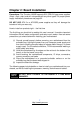
Chapter 4: Diagnostics Note: if you experience problems with setting up your system, always check the following things in the following order: Memory, Video, CPU By checking these items, you will most likely find out what the problem might have been when setting up your system. For more information on troubleshooting, check the TYAN website at: http://www.tyan.com. 4.1 Flash Utility Every BIOS file is unique for the motherboard it was designed for.
4.
2Fh 30h Code 6Ah 6Bh 6Ch 6Eh 70h 72h 76h 7Ch 7Eh 80h 81h 82h 83h 84h 85h 86h. 87h 88h 89h 8Ah 8Bh 8Ch 8Fh 90h 91h 92h data bits of low byte of memory bus Enable cache before system BIOS shadow 1-4-1-1.
93h 95h 96h Build MPTABLE for multiprocessor boards Install CD ROM for boot C8h C9h D2h Extended checksum (optional) BIOS Boot Block E0h E1h BIOS Boot Block BIOS Boot Block E2h Initialize the CPU E3h E4h E5h Initialize system timer Initialize system I/O Check force recovery boot E6h E7h Checksum BIOS ROM Go to BIOS E8h Code F1h F2h F3h Set Huge Segment Beeps / Description Initialize Run Time Clock Initialize video Initialize System Management Mode Output one beep before boot Boot to Mini DOS Cl
Appendix I: How to Make a Driver Diskette Follow the steps below to make a driver diskette from the TYAN driver CD provided. 1. Start the system and insert the TYAN CD into the CD-ROM drive to boot from CD. You will see the following menu. Then press [1] and [Enter] to boot the system to TYAN diskette maker. (If you would like to boot from hard disk, press 0 and Enter or just wait for 10 seconds to boot automatically from hard disk.). Boot from CD: ISOLINUX 2.00 2002-10-25 Copyright (C) 1994-2002 H.
3. The following picture pops up after selecting the chipset model. TYAN Driver Diskette Maker ** nVidia** ====Choose Chipset Model==== 01 nVidia NVRAID EXIT 4. After selecting the chipset model, select the OS to start the diskette making. TYAN Driver Diskette Maker ====nVidia NVRAID SATA and RAID Driver==== Diskette Diskette Diskette Diskette =01= =02= =03= =04= Microsoft Windows 2000 32-bit Microsoft Windows XP 32-bit Microsoft Windows XP 64bit Microsoft Windows 2003 64-bit Back 5.
Glossary ACPI (Advanced Configuration and Power Interface): a power management specification that allows the operating system to control the amount of power distributed to the computer’s devices. Devices not in use can be turned off, reducing unnecessary power expenditure. AGP (Accelerated Graphics Port): a PCI-based interface which was designed specifically for demands of 3D graphics applications. The 32-bit AGP channel directly links the graphics controller to the main memory.
losing your data should the system crash. Information in a buffer is temporarily stored, not permanently saved. Bus: a data pathway. The term is used especially to refer to the connection between the processor and system memory, and between the processor and PCI or ISA local buses. Bus mastering: allows peripheral devices and IDEs to access the system memory without going through the CPU (similar to DMA channels). Cache: a temporary storage area for data that will be needed often by an application.
DRAM (Dynamic RAM): widely available, very affordable form of RAM which looses data if it is not recharged regularly (every few milliseconds). This refresh requirement makes DRAM three to ten times slower than non-recharged RAM such as SRAM. ECC (Error Correction Code or Error Checking and Correcting): allows data to be checked for errors during run-time. Errors can subsequently be corrected at the same time that they’re found.
I/O (Input/Output): the connection between your computer and another piece of hardware (mouse, keyboard, etc.) IRQ (Interrupt Request): an electronic request that runs from a hardware device to the CPU. The interrupt controller assigns priorities to incoming requests and delivers them to the CPU. It is important that there is only one device hooked up to each IRQ line; doubling up devices on IRQ lines can lock up your system. Plug-n-Play operating systems can take care of these details for you.
PXE (Preboot Execution Environment): one of four components that together make up the Wired for Management 2.0 baseline specification. PXE was designed to define a standard set of preboot protocol services within a client with the goal of allowing networked-based booting to boot using industry standard protocols. RAID (Redundant Array of Independent Disks): a way for the same data to be stored in different places on many hard drives.
SDRAM (Static RAM): unlike DRAM, this type of RAM does not need to be refreshed in order to prevent data loss. Thus, it is faster and more expensive. Standby mode: in this mode, the video and hard drives shut down; all other devices continue to operate normally. UltraDMA-33/66/100: a fast version of the old DMA channel. UltraDMA is also called UltraATA. Without a proper UltraDMA controller, your system cannot take advantage of higher data transfer rates of the new UltraDMA/UltraATA hard drives.
Technical Support If a problem arises with your system, you should turn to your dealer for help first. Your system has most likely been configured by them, and they should have the best idea of what hardware and software your system contains. Furthermore, if you purchased your system from a dealer near you, you can bring your system to them to have it serviced instead of attempting to do so yourself (which can have expensive consequences).
NOTE: A receipt or copy of your invoice marked with the date of purchase is required before any warranty service can be rendered. You may obtain service by calling the manufacturer for a Return Merchandise Authorization (RMA) number. The RMA number should be prominently displayed on the outside of the shipping carton and the package should be mailed prepaid. TYAN will pay to have the board shipped back to you.