Thunder n3600QX /// S4987 Version 1.00 Copyright Copyright © TYAN Computer Corporation, 2007. All rights reserved. No part of this manual may be reproduced or translated without prior written consent from TYAN Computer Corp. Trademark All registered and unregistered trademarks and company names contained in this manual are property of their respective owners including, but not limited to the following. TYAN, Thunder n3600QX are trademarks of TYAN Computer Corporation.
Table of Contents Before you begin 4 Chapter 1: Introduction 1.1 Congratulations………………….…………………….……...…….… 5 1.2 Hardware Specifications…..……..……………………….………....... 5 1.3 Software Specifications………………………………………………. 7 Chapter 2: Board Installation 2.1 Board Image…………………….….…………………………………. 2.2 Block Diagram………………….….…………………………………. 2.3 Board Parts, Jumpers and Connectors……….….……………………. 2.4 Installing the Processors.……….….…………………………………. 2.5 Heat Sink Installing……….……….…………………………………. 2.
.9.2 3.9.3 3.9.4 3.9.5 Boot Device Priority………………..………………………….............. Hard Disk Drives……………...……………………………….............. Removable Drives…………..…………………………………………. Network Drives..……………………………………………………….. 3.10 Security Menu……………………………………………………….. 3.11 Chipset Menu………………………………………………………... 3.11.1 Northbridge Configuration Sub-Menu………………………………… 3.11.2 Southbridge Configuration Sub-Menu………………………………… 3.11.3 Hyper Transport MCP55 Configuration Sub-Menu…………………… 3.
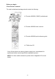
Before you begin… Check the box contents! The retail motherboard package should contain the following: 1 x Thunder n3600QX (S4987) motherboard 1 x Thunder n3600QX user’s manual 1 x Thunder n3600QX quick reference guide 1 x TYAN driver CD If any of these items are missing, please contact your vendor/dealer for replacement before continuing with the installation process. NOTE: For other usable accessories, please refer to Appendix IV for more details.
Chapter 1: Instruction 1.1 - Congratulations You have purchased one of the most powerful server solutions. Based on NVIDIA nForce Pro3600 chipset, the Thunder n3600QX (S4987) is designed to ® support AMD Opteron™ Socket F (1207) 8000 series dual-core and Quadcore processors and up to 128GB DDRII-667 memory, providing a rich feature set and incredible performance.
Integrated SAS Controller LSI 1068E SAS controller ● PCI-E x4 interface ● Supports eight SAS ports (4 ports internal, 4 ports external) ● RAID 0,1, and 1E supported pin header Four SAS ports ● Four SATA ports ● One IDE connector ● Two USB headers ● One COM port header at 3.
1.3 - Software Specifications For OS (operation system) support, please check with Tyan support for latest information.
Chapter 2: Board Installation You are now ready to install your motherboard. How to install our products right… the first time The first thing you should do is reading this user’s manual. It contains important information that will make configuration and setup much easier. Here are some precautions you should take when installing your motherboard: (1) Ground yourself properly before removing your motherboard from the antistatic bag.
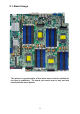
2.1- Board Image This picture is representative of the latest board revision available at the time of publishing. The board you receive may or may not look exactly like the above picture.
2.
2.3 - Board Parts, Jumpers and Connectors This diagram is representative of the latest board revision available at the time of publishing. The board you receive may not look exactly like the above diagram. But for the DIMM number please refer to the above placement for memory installation. For the latest board revision, please visit: www.tyan.
Jumpers & Connectors Jumper/Connector Function J3 Front Panel Header (14Pin x 2) J5 IPMB Pin Header (4Pin x 1) J12 USB Pin Header (5Pin x 2) J18 LCM Pin Header (3Pin x 2) J29 FAN Tach Connector (9Pin x 2) J19/J21/J22/J24/J39 FAN Connector (4Pin x 1) J35 M2061 PWR Connector (4Pin x 1) J36/J37 SAS SGPIO Connector (3Pin x 2) J38 SAS Fault LED Connector (5Pin x 2) JP3/JP4 OPMA Setting Jumper (2Pin) JP8 Clear CMOS (3Pin) JP9 Chassis Intrusion Header (2Pin) Jumper Legend OPEN - Jumper OF
Jumper Placement J3 J5 J18 J29 J12 J3: Front Panel Connector (14Pin x 2) Signal HD LED+ Reset Button+ PW LED+ Fault LED+ SM BUS DATA NMI Button 5VSB PWR Button+ LAN2 LED+ LAN1 LED+ Reserve ID LED+ ID LED Button+ KEY PIN Pin 1 3 5 7 9 11 13 15 17 19 21 23 25 27 Pin 2 4 6 8 10 12 14 16 18 20 22 24 26 28 13 Signal HD LEDReset ButtonPW LEDFault LEDSM BUS CLK NMI ButtonINTRUDER# PWR ButtonLAN2 LEDLAN1 LEDReserve ID LEDID LED ButtonNC
J5: IPMB Pin Header (4Pin x 1) Signal IPMB DATA IPMB CLK Pin 1 3 Pin 2 4 Signal GND NC J12: USB Pin Header (5Pin x 2) Signal Pin Pin +5VPWR 1 2 DATA13 4 DATA1+ 5 6 GND 7 8 Key 9 10 Use this header to connect to the USB devices via the enclosed USB cable. Signal +5VPWR DATA2DATA2+ GND GND J18: LCM Pin Header (3Pin x 2) Signal Pin Pin VCC_5_RUN 1 2 KEY PIN 3 4 VCC_5_DUAL 5 6 Use this header to connect the LCM module with system monitoring function.
J22 J24 J19 J21 J39 J19/J21/J22/J24/J39: FAN Connector (4Pin x 1) Pin_1 Pin Signal 1 PWM 2 TACH 3 +12V 4 GND NOTE: Pin 1 is not used when the FAN only have three pins.
JP3 JP4 JP9 J36/J37 J38 J35 JP8 J35: M2061 PCI-E to PCI-X Riser Connector (4Pin x 1) Pin_1 Pin Signal 1 N/C 2 GND 3 GND 4 VDD_5_RUN J36/J37: SAS SGPIO Connector (3Pin x 2) Signal SAS_SIO_DIN SAS_SIO_CLK KEY PIN Pin 1 3 5 16 Pin 2 4 6 Signal SAS_SIO_DOUT GND SAS_SIO_END
J38: SAS Fault LED Connector (5Pin x 2) Signal Pin Signal 1 2 3 4 5 6 KEY PIN 7 8 SAS_FAULT_L ED_N1 SAS_FAULT_L ED_N3 SAS_FAULT_L ED_N5 SAS_FAULT_L ED_N7 SAS_FAULT_L ED_N6 9 10 GND SAS_FAULT_L ED_N0 SAS_FAULT_L ED_N2 SAS_FAULT_L ED_N4 Pin JP3/JP4: OPMA Setting Jumper (2Pin) Install: TYAN OPMA Card (Default) Remove: Other OPMA Card JP8: Clear CMOS Pin_3 Pin_1 Normal (Default) Pin_3 Pin_1 Clear CMOS You can reset the CMOS settings by using this jumper if you have forgotten your syste
2.4 - Installing the Processor Your brand new Thunder n3600QX (S4987) supports the latest 64-bit processor ® ® technology from AMD . Only AMD Opteron™ Socket F 8000 series processors are certified and supported with this motherboard. Check our website for latest processor support. http://www.tyan.com TYAN is not liable for damage as a result of operating an unsupported configuration.
2.5 - Heat sink Installation After installing the processor, you should proceed to install the heat sink. The CPU heat sink will ensure that the processor do not overheat and continue to operate at maximum performance for as long as you own them. The overheated processor is dangerous to the motherboard. For the safest method of installation and information on choosing the appropriate heat sink, use heat sinks validated by AMD. Please refer to AMD’s website at www.amd.com.
2.6 - Thermal Interface Material There are two types of thermal interface materials designed for use with the AMD® Opteron™ processors. The most common material comes as a small pad attached to the heat sink at the time of purchase. There should be a protective cover over the material. Take care not to touch this material. Simply remove the protective cover and place the heat sink on the processor. The second type of interface material is usually packaged separately.
2.7 - Finishing Installing the Heat sink After you have finished installing the heat sink onto the processor and socket, attach the end wire of the fan (which should already be attached to the heat sink) to the motherboard. The following diagram illustrates how to connect fans onto the motherboard. Once you have finished installing all the fans you can connect your drives (hard drives, CD-ROM drives, etc.) to your motherboard.
2.8 - Tips on Installing Motherboard in Chassis Before installing your motherboard, make sure your chassis has the necessary motherboard support studs installed. These studs are usually metal and are gold in color. Usually, the chassis manufacturer will pre-install the support studs. If you are unsure of stud placement, simply lay the motherboard inside the chassis and align the screw holes of the motherboard to the studs inside the case.
Some chassis’ include plastic studs instead of metal. Although the plastic studs are usable, TYAN recommends using metal studs with screws that will fasten the motherboard more securely in place. Below is a chart detailing what the most common motherboard studs look like and how they should be installed.
2.9 - Installing the Memory Before installing memory, ensure that the memory you have is compatible with the motherboard and processor. Check the TYAN Web site at: www.tyan.com for details of the type of memory recommended for your motherboard. The following diagram shows common types of DDR2 memory modules. • • • • AMD Opteron™ processors support 64bit (non-interleaved) or 128bit (interleaved) memory configuration. ECC Registered DDRII-400/533/667 memory modules are supported.
Dual CPU installed (CPU0 and CPU1) Single CPU Installed (CPU0 only) Quantity of memory installed 2 4 8 4 8 Four CPU installed 16 8 16 32 CPU0_DIMM1(A) √ √ √ CPU0_DIMM2(B) √ √ √ CPU0_DIMM3(A) √ √ √ CPU0_DIMM4(B) √ √ √ CPU0_DIMM5(A) √ √ √ √ √ CPU0_DIMM6(B) √ √ √ √ √ √ √ CPU0_DIMM7(A) √ √ √ √ √ √ √ √ √ CPU0_DIMM8(B) √ √ √ √ √ √ √ √ √ CPU1_DIMM9(A) √ √ CPU1_DIMM10(B) √ √ CPU1_DIMM11(A) √ √ CPU1_DIMM12(B) √ √ CPU1_DIMM13(A) √ √ √ CPU1_
Memory Installation Procedure Follow these instructions to install memory modules into the Thunder n3600QX. 1. Press the locking levers in the direction shown in the following illustration. 2. Align the memory module with the socket. The memory module is keyed to fit only one way in the socket. Key slot 3. Seat the module firmly into the socket by gently pressing down until it sits flush with the socket. The locking levers pop up into place.
2.10 - Attaching Drive Cables Attaching IDE Drive Cable Attaching the IDE drive cable is simple. These cables are “keyed” to only allow them to be connected in the correct manner. TYAN motherboards have two on-board IDE channels, each supporting two drives. The black connector designates the Primary channel, while the white connector designates the Secondary channel.
The following pictures illustrate how to connect an SATA drive 1. SATA drive cable connection 2. SATA drive power connection 3. SATA cable motherboard connector 4. SATA drive power adapter Attaching Floppy Drive Cables Attaching floppy diskette drives are done in a similar manner to hard drives. See the picture below for an example of a floppy cable. Most of the current floppy drives on the market require that the cable be installed with the colored stripe positioned next to the power connector.
2.11 - Installing Add-In Cards Before installing add-in cards, it’s helpful to know if they are fully compatible with your motherboard. For this reason, we’ve provided the diagrams below, showing the slots that may appear on your motherboard. PCI-E x 16 slot HTX slot SO-DIMM slot Simply find the appropriate slot for your add-in card and insert the card firmly. Do not force any add-in cards into any slots if they do not seat in place.
2.12 - Installing SO-DIMM Modules - OPMA Card Your Thunder n3600QX (S4987) motherboard is equipped with a proprietary SO-DIMM connector. The SO-DIMM connector plays the role of OPMA rd connector and supports Tyan M3295 M2 card and 3 party M3 OPMA card. Follow these steps to install the OPMA Card (M3295) into the SO-DIMM slot. SO-DIMM Socket M3295 1. Insert OPMA Card (M3295) firmly into the socket by pressing down as shown in the diagram.
2.13 - Connecting External Devices Your motherboard supports a number of different interfaces through connecting peripherals. See the following diagrams for the details. PS/2 Mouse/Keyboard LAN Port x 2 Serial Port VGA Port ID SW USB Port x 2 ID LED SAS LED IB Active LED OPMA Port IB CON SAS CON IB Power LED NOTE: Peripheral devices can be plugged straight into any of these ports but software may be required to complete the installation.
2.14 - Installing the Power Supply There are six power connectors on your Thunder n3600QX (S4987). The Thunder n3600QX (S4987) supports 12V and 5.5V SB input DPS power supplies, please use below combination: PWR3/7/8: 4-Pin PWR Connector reserved for Tyan 2U Barebone only PWR4: 4-Pin PWR Connector for Tyan M1223 only Refer to Diagram B for each power location.
PWR6: Power Connector for Tyan M1221 only (4Pin x 2) Signal GND GND GND GND Pin 1 2 3 4 Pin 5 6 7 8 Signal +12V +12V +5V +3.3V PWR2: PWR Main Connector P1 +12V P2 +12V P3 +12V P4 GND P5 GND P6 GND Signal Signal P7 GND P8 Neutral P9 90~264V Pin 9: 90~264V Pin 8: Neutral Pin 7: GND We suggest using a 1000W or higher power supply; this of course depends on how many devices you attach.
Chapter 3: BIOS Setup 3.1 About the BIOS The BIOS is the basic input/output system, the firmware on the motherboard that enables your hardware to interface with your software. The BIOS determines what a computer can do without accessing programs from a disk. The BIOS contains all the code required to control the keyboard, display screen, disk drives, serial communications, and a number of miscellaneous functions. This chapter describes the various BIOS settings that can be used to configure your system.
3.3 Setup Basics The table below shows how to navigate in the setup program using the keyboard. Key Å Æ arrow keys ↑ or ↓ arrow keys or or or <-> <+> 3.
3.6 BIOS Main Menu The Main BIOS Menu is the first screen that you can navigate. The Main BIOS setup menu screen has two main frames. The left frame displays all the options that can be configured. "Grayed-out" options cannot be configured, options in blue can be changed. The right frame displays the key legend. Above the key legend is an area reserved for a text message. When an option is selected in the left frame, it is highlighted in white. Often, a text message will accompany it.
3.7 BIOS Advanced Menu You can select any of the items in the left frame of the screen, such as Super I/O Configuration, to go to the sub menu for that item. You can display an Advanced BIOS Setup option by highlighting it using the keys. All Advanced BIOS Setup options are described in this section. The Advanced BIOS Setup screen is shown below. The sub menus are described on the following pages.
3.7.1 CPU Configuration You can use this screen to view CPU Configuration Menu. Use the up and down arrow (Ç/È) keys to select an item. Use the Plus and Minus (+/-) keys to change the value of the selected option. The settings are described on the following pages. Main Advanced BIOS Setup Utility PCI/PnP Boot Security Chipset Exit This option should remain disabled for normal operation. The driver developer may disable it for testing purpose. CPU Configuration Module Version : XX.
Feature CPU Configuration Option Description Module Version AGESA Version Physical Count Read only Displays information about CPU Read only Displays information about CPU Disabled This option should remain disabled for normal operation. The driver developer may enable it for the purpose of testing. Logical Count Revision Cache L1 Cache L2 Speed Current FSB Multiplier Maximum FSB Multiplier Able to change Freq.
3.7.2 IDE Configuration Sub-Menu You can use this screen to select options for the IDE Configuration Settings. Use the up and down Keys to select an item. Use the and Keys to change the value of the selection options.
3.7.2.1 nVidia RAID Setup Feature Main Advanced Option Description BIOS Setup Utility PCI/PnP Boot Security RAID Setup nVidia RAID Function [Disabled] SATA0 SATA1 SATA2 SATA3 [Disabled] [Disabled] [Disabled] [Disabled] (Dev 5, Func0) (Dev 5, Func0) (Dev 5, Func1) (Dev 5, Func1) Chipset Exit While entering setup, BIOS auto detects the presence of IDE devices. This displays the status of auto detection of IDE devices.
3.7.2.2 Primary IDE Master/Slave Sub-Menu Main Advanced Primary IDE Master BIOS Setup Utility PCI/PnP Boot Security Chipset Exit Device: Not Detected [Auto] [Auto] [Auto] [Auto] [Auto] [Auto] [Enabled] Type LBA /Large Mode Block (Multi-Sector Transfer) PIO Mode DMA Mode S.M.A.R.T.
3.7.2.3 SATA0/1/2/3 Sub-Menu Main Advanced Third IDE Master BIOS Setup Utility PCI/PnP Boot Security Chipset Exit Device: Not Detected [Auto] [Auto] [Auto] [Auto] [Auto] [Enabled] LBA /Large Mode Block (Multi-Sector Transfer) PIO Mode DMA Mode S.M.A.R.T. 32 Bit Data Transfer Feature SATA 0/1/2/3 Option Auto LBA/Large Mode Disabled Auto Block (Multi-Sector Transfer) Disabled Auto PIO Mode 0~4 (at 1 interval) DMA Mode Auto S.M.A.R.T.
3.7.3 Super I/O Configuration Sub-Menu You can use this screen to select options for the Super I/O settings. Use the up and down arrow (Ç/È) keys to select an item. Use the Plus and Minus (+/-) keys to change the value of the selected option.
3.7.4 ACPI Configuration Sub-Menu Use this screen to select options for ACPI. Use the up and down arrow (Ç/È) keys to select an item. Use the Plus and Minus (+/-) keys to change the value of the selected option. A description of the selected item appears on the right side of the screen. The settings are described on this page. The screen is shown below.
3.7.4.1 Advanced ACPI Configuration Sub-Menu Main Advanced BIOS Setup Utility PCI/PnP Boot Security Chipset Exit Advanced ACPI Configuration ACPI Version Features ACPI APIC support AMI OEMB table Headless mode Feature Advanced ACPI Configuration [ACPI v1.0] [Enabled] [Enabled] [Disabled] Option ACPI v3.0 ACPI Version Features ACPI v2.0 ACPI v1.
3.7.4.2 Chipset ACPI Configuration Sub-Menu Main Advanced BIOS Setup Utility PCI/PnP Boot Security Chipset Exit Chipset ACPI Configuration MCP55 ACPI HPET Table Feature Chipset ACPI Configuration MCP55 ACPI HPET Table [Enabled] Option Enabled Disabled 47 ← → Select Screen ↑↓ Select Item +/- Change Option F1 General Help F10 Save and Exit ESC Exit Description Enable/Disable MCP55 ACPI HPET Table.
3.7.
Feature Option Description APM Configuration Power Management/APM Power Button Mode Video Power Down Mode Green PC Monitor Power State Hard Disk Power Down Mode Hard Disk Time Out (Minute) Force Throttle Manual Throttle Ratio System Thermal Thermal throttle Ratio Resume On PME# Resume On PCIE Wake Enabled Disabled On/Off suspend Enabled Disabled Standby Suspend Off Enabled Disabled 1 2 3 4 5 6 7 8 9 10 11 12 13 14 15 Disabled Enabled Disabled 87.5% 75% 62.5% 50% 37.5% 25% 12.
Resume On LAN (MAC) Resume On Ring Resume On PS/2 Keyboard Resume On RTC Alarm Enabled Disabled Enabled Disabled Enabled Disabled Enabled Disabled Disable/Enable LAN(MAC) to generate a wake event. Disable/Enable RI to generate a wake event. Disable/Enable PS/2 Keyboard to generate a wake event. Disable/Enable RTC event to wake after a power failure. 3.7.6 Event Log Configuration Sub-Menu You can use this screen to view the Event Log Control Menu.
3.7.7 Hardware Health Configuration Sub-Menu You can use this screen to view the Hardware Health Configuration Settings. Use the up and down arrow (Ç/È) keys to select an item. Use the Plus and Minus (+/-) keys to change the value of the selected option. The settings are described on the following pages.
3.7.7.
3.7.7.
3.7.8 Remote Access Configuration Sub-Menu You can use this screen to view the Remote Access Configuration Menu. This feature allows access to the Server remotely via serial port. Use the up and down arrow (Ç/È) keys to select an item. Use the Plus and Minus (+/-) keys to change the value of the selected option. The settings are described on the following pages.
3.7.9 USB Configuration Sub-Menu You can use this screen to view the USB Configuration Menu. Use the up and down arrow (Ç/È) keys to select an item. Use the Plus and Minus (+/-) keys to change the value of the selected option. The settings are described on the following pages. Main Advanced BIOS Setup Utility PCI/PnP Boot Security Chipset Exit Enables support for legacy USB. USB Configuration Module Version – X.XX.X-XX.X USB Devices Enabled: None Legacy USB Support USB 2.
3.7.9.
3.8 PCI PnP Menu You can use this screen to view PnP (Plug & Play) BIOS Configuration Menu. This menu allows the user to configure how the BIOS assigns resources & resolves conflicts. Use the up and down arrow (Ç/È) keys to select an item. Use the Plus and Minus (+/-) keys to change the value of the selected option. The settings are described on the following pages. Main Advanced BIOS Setup Utility PCI/PnP Boot Security Chipset Exit Clear NVRAM during System Boot.
Feature Advanced PCI/PnP Settings Clear NVRAM Option Description No Yes Clears NVRAM during system Boot. No: lets the BIOS configure all the devices in the system. Yes: lets the operating system configure Plug and Play (PnP) devices not required for boot if your system has a Plug and Play operating system. This setting controls how many PCI clocks each PCI device can hold the bus before another PCI device takes over.
3.9 Boot Menu You can display Boot Setup option by highlighting it using the Arrow (Ç/È) keys and pressing Enter. The settings are described on the following pages. Main Advanced BIOS Setup Utility PCI/PnP Boot Security Chipset Exit Boot Settings Configures settings during System Boot. Boot Settings Configuration ← → Select Screen ↑↓ Select Item Enter Go to Sub Screen F1 General Help F10 Save and Exit ESC Exit Boot Device Priority Hard Disk Drives Removable Drives Network Drives 3.9.
Feature Option Description Boot Settings Configuration Quick Boot Enabled Disabled Disabled Quiet Boot Enabled Add On ROM Display Mode Boot up Num-Lock PS/2 Mouse Support Wait for ‘F1’ If Error Hit ‘DEL’ Message Display Interrupt 19 Capture Endless Boot Force BIOS Keep Current On Off Enabled Disabled Auto Enabled Disabled Enabled This option allows user bypass BIOS self test during POST. Disabled: displays normal POST messages. Enabled: displays OEM log instead of POST messages.
3.9.2 Boot Device Priority Use this screen to select options for the Boot Device Priority. Use the up and down arrow (Ç/È) keys to select an item. Use the Plus and Minus (+/-) keys to change the value of the selected option. Main Advanced BIOS Setup Utility PCI/PnP Boot Security Boot Device Priority 1st Boot Device 2nd Boot Device [xx,xxx-xxxxx:xxx] [xx,xxx-xxxxx:xxx] Chipset Exit Specifies the boot sequence from the available devices.
3.9.3 Hard Disk Drives Main Advanced BIOS Setup Utility PCI/PnP Boot Security Hard Disk Drives 1st Drive [xx,xxx-xxxxx:xxx] Chipset Exit Specifies the boot sequence from the available devices. ← → Select Screen ↑↓ Select Item +/- Change Option F1 General Help F10 Save and Exit ESC Exit Feature Hard Disk Drives 1st Drive Option Description xx,xxx-xxxxx:xxx Specifies the boot sequence from the available devices.
3.9.4 Removable Drives Main Advanced BIOS Setup Utility PCI/PnP Boot Security Exit Specifies the boot sequence from the available devices. Removable Drives 1st Drive Chipset [xx,xxx-xxxxx:xxx] ← → Select Screen ↑↓ Select Item +/- Change Option F1 General Help F10 Save and Exit ESC Exit Feature Network Drives 1st Drive 3.9.5 Option Description xx,xxx-xxxxx:xxx Specifies the boot sequence from the available devices.
3.10 Security Menu The system can be configured so that all users must enter a password every time the system boots or when BIOS Setup is entered, using either the Supervisor password or User password. The Supervisor and User passwords activate two different levels of password security. If you select password support, you are prompted for a one to six character password. Type the password on the keyboard. The password does not appear on the screen when typed. Make sure you write it down.
3.11 Chipset Menu This menu allows the user to customize functions of the AMD Chipsets. North Bridge configuration contains options for Memory & CPU settings. South Bridge configuration contains options for SM Bus & USB. Additional configuration for the AMD8131 PCI-X Tunnel is available in the PCI-X Configuration Menu. Select a menu by highlighting it using the Arrow (Ç/È) keys and pressing Enter. The settings are described on the following pages.
3.11.1 Northbridge Configuration Sub-Menu This menu gives options for customizing memory & Hypertransport settings. Select a menu by highlighting it using the Arrow (Ç/È) keys and pressing Enter. The settings are described on the following pages.
Feature Option NorthBridge Chipset Configuration CAS Latency (Tcl) This controls the timing delay (in clock cycles) before SDRAM starts a read command after receiving it. Read only RAS/CAS Delay (Trcd) Read only Min Active RAS (Tras) Read only Row Precharge Time (Trp) Read only RAS/RAS Delay (Trrd) Description When DRAM is refreshed, both rows and columns are addressed separately.
3.11.1.1 Memory Configuration Sub-Menu This menu has options for memory speed & latency. Use the up and down arrow (Ç/È) keys to select an item. Use the Plus and Minus (+/-) keys to change the value of the selected option.
Feature Memory Configuration Option Limit Memclock Mode Auto Manual Memory Clock Value MCT Timing Mode CAS Latency (CL) TRAS TRP TRCD TRRD TRC Bank Interleaving Enable Clock to All DIMMs MemClk Tristate C3/ATLVID Disabled Enabled Disabled Enabled Disabled CS Spuring Enable DQS Signal Control 400 533 667 800 Manual Auto Auto 3.0 ~ 6.
3.11.1.2 ECC Configuration Sub-Menu This menu allows the user to configure ECC setup for system & DRAM. Use the up and down arrow (Ç/È) keys to select an item. Use the Plus and Minus (+/-) keys to change the value of the selected option.
Feature ECC Configuration Data Cache BG Scrub Option 80ns 160ns 320ns 640ns 1.28us 2.56us 5.12us 10.2us 20.5us 41.0us 81.9us 163.8us 327.7us 655.4us Disabled 40ns 80ns 160ns 320ns 640ns 1.28us 2.56us 5.12us 10.2us 20.5us 41.0us 81.9us 163.8us 327.7us 655.4us Description Allows the L1 Data Cache RAM to be corrected while idle.
3.11.1.3 IOMMU Option Menu This menu has options for IOMMU. Use the up and down arrow (Ç/È) keys to select an item. Use the Plus and Minus (+/-) keys to change the value of the selected option. Main Advanced IOMMU Mode BIOS Setup Utility PCI/PnP Boot Security [AGP Present] Chipset Exit Set GART size in systems without AGP, or disable altogether. Some OSes require valid GART for proper operation, If AGP is present, select appropriate option to ensure proper AGP operation.
3.11.2 Southbridge Configuration Sub-Menu This menu gives options for southbridge devices settings. Select a menu by highlighting it using the Arrow (Ç/È) keys and pressing Enter. The settings are described on the following pages. Main Advanced BIOS Setup Utility PCI/PnP Boot Security Chipset Exit SouthBridge Chipset Configuration CPU/LDT Spread Spectrum PCIE Spread Spectrum SATA Spread Spectrum [Center Spread] [Enabled] [Enabled] Primary Graphics Adapter USB1.1 Controller USB2.
3.11.3 Hyper Transport MCP55 Configuration Sub-Menu This menu gives Hyper Transport Links settings. Select a menu by highlighting it using the Arrow (Ç/È) keys and pressing Enter. The settings are described on the following pages.
3.12 Exit Menu You can display an Exit BIOS Setup option by highlighting it Arrow (Ç/È) keys and pressing Enter. Main Advanced BIOS Setup Utility PCI/PnP Boot Security Chipset Exit Exit Options Exit system setup after saving the changes. Save Changes and Exit Discard Changes and Exit Discard Charges F10 key can be used for this operation.
NOTE 76
Chapter 4: Diagnostics NOTE: if you experience problems with setting up your system, always check the following things in the following order: Memory, Video, CPU By checking these items, you will most likely find out what the problem might have been when setting up your system. For more information on troubleshooting, check the TYAN website at: http://www.tyan.com. 4.1 Beep Codes Fatal errors, which halt the boot process, are communicated through two kinds of audible beeps.
4.3 AMIBIOS Post Code The POST code checkpoints are the largest set of checkpoints during the BIOS pre-boot process. The following table describes the type of checkpoints that may occur during the POST portion of the BIOS: Checkpoint 03 04 05 06 08 0A 0B 0C 0E 13 24 30 2A 2C 2E 31 33 37 Description Disable NMI, Parity, video for EGA, and DMA controllers. Initialize BIOS, POST, Runtime data area. Also initialize BIOS modules on POST entry and GPNV area.
Checkpoint 38 39 3A 3B 3C 40 50 52 60 75 78 7A 7C 84 85 87 8C 8E 90 A0 A1 A2 A4 A7 A8 A9 AA AB AC B1 00 Description Initializes different devices through DIM. See DIM Code Checkpoints section of document for more information. Initializes DMAC-1 & DMAC-2. Initialize RTC date/time. Test for total memory installed in the system. Also, Check for DEL or ESC keys to limit memory test. Display total memory in the system. Mid POST initialization of chipset registers.
Appendix I: How to Make a Driver Diskette Follow the steps below to make a driver diskette from the TYAN driver CD provided. 1. Start the system and insert the TYAN CD into the CD-ROM drive to boot from CD. You will see the following menu. Then press [1] and [Enter] to boot the system to Tyan diskette maker. (If you would like to boot from hard disk, press 0 and Enter or just wait for 10 seconds to boot automatically from hard disk.). Boot from CD: ISOLINUX 2.00 2002-10-25 Copyright (C) 1994-2002 H.
3. The following picture pops up after selecting the chipset model. TYAN Driver Diskette Maker ** nVidia ** ====Choose Chipset Model==== 01 nVidia NVRAID EXIT 4. After selecting the chipset model, select the OS to start the diskette making. TYAN Driver Diskette Maker ====Example Chipset Driver==== Diskette Diskette Diskette Diskette =01= =02= =03= =04= Microsoft Windows 2000 32-bit Microsoft Windows XP 32-bit Microsoft Windows XP 64bit Microsoft Windows 2003 64-bit Back 5.
Appendix II: LSI Logic Config Utility NOTE: This appendix just provides a brief introduction of the LSI Logic integrated RAID solution for LSI Logic controller LSISAS 1068E. For detail of SAS RAID (S4987), please visit http://www.Lsilogic.com/contacts/index.html to refer to LSI manual.
Figure X.2 On the Adapter properties screen, use the arrow keys to select RAID Properties on the screen and press . When you are prompted to select a volume type, select Create XX (such as IM, IME or IS) volume as shown in figure X.3. The create New Array screen illustrates a list of disks that can be added to a volume. Figure X.3 5. Move the cursor to the “RAID disk” column to select a disk. To add a disk to the volume, change the “NO” to “YES” by pressing “+ Key”, “- Key”, or “space bar”. 5.
existing data on the first disk or press “D” to overwrite it. If you keep the existing data, this is called a migration. The first disk will be mirrored onto the second one, so the data you want to keep must be on the first disk added to the volume. And in this way, any data on the second disk is overwritten. 5.2 Creating an IME (RAID 1E) volume: Repeat this step to select a total of three to eight disks for the volume (or three to seven disks if you will create a global hot spare). 5.
Appendix III: InfiniBand Installation Guide InfiniBand™ enabling, Optional for S4987WG2NGI2 only Note: The appendix just gives a draft picture of the InfiniBand™ driver installation, for the detail please visit http://www.mellanox.com/ to download the latest InfiniBand Driver and users’ manual. The InfiniBand™ Architecture (IBA) is an industry standard that defines a new high-speed switched fabric subsystem designed to connect processor nodes and I/O nodes to form a system area network.
The following diagrams may guide you how to install the InfiniBand Driver.
Registration Info Install Path SDP/WSD Activation 87
Complete/Custom Components Selection. Only SDP or WSD may be installed.
SDP/WSD Activation The installer installs 3 types of devices: – InfiniBand Fabric – HCA – IPoIB Interface 89
Uninstall InfiniBand Driver z z Uninstall can be done from the “Add/Remove Program” of the control panel or from the “Start -> Programs -> Mellanox -> WinIB”; After the uninstall one MUST restart the machine to complete the uninstall process; 90
Appendix IV: Recommended Accessory List For integrating your Thunder n3600QX (S4987) into a 1U/2U system, you can either equip your S4987 with the Tyan Barebone qualified accessories or use others with the same specification as a reference. Power Supply Unit Below is detailed information of recommended power supply unit. You may contact COLDWATT (PSU vendor) directly if having any interest: www.coldwatt.
If you are interested in Tyan 1U GT26-B4987 accessory list, please visit http://www.tyan.com/support_download_fru.aspx?model=B.GT26B4987 for details. For the Tyan 2U TN27-B4987 accessory list (not available at the time of print), please visit www.tyan.com for further details.
Glossary ACPI (Advanced Configuration and Power Interface): a power management specification that allows the operating system to control the amount of power distributed to the computer’s devices. Devices not in use can be turned off, reducing unnecessary power expenditure. AGP (Accelerated Graphics Port): a PCI-based interface which was designed specifically for demands of 3D graphics applications. The 32-bit AGP channel directly links the graphics controller to the main memory.
Bus: a data pathway. The term is used especially to refer to the connection between the processor and system memory, and between the processor and PCI or ISA local buses. Bus mastering: allows peripheral devices and IDEs to access the system memory without going through the CPU (similar to DMA channels). Cache: a temporary storage area for data that will be needed often by an application. Using a cache lowers data access times since the information is stored in SRAM instead of slower DRAM.
ECC (Error Correction Code or Error Checking and Correcting): allows data to be checked for errors during run-time. Errors can subsequently be corrected at the same time that they’re found. EEPROM (Electrically Erasable Programmable ROM): also called Flash BIOS, it is a ROM chip which can, unlike normal ROM, be updated. This allows you to keep up with changes in the BIOS programs without having to buy a new chip. TYAN’s BIOS updates can be found at http://www.tyan.
up your system. Plug-n-Play operating systems can take care of these details for you. Latency: the amount of time that one part of a system spends waiting for another part to catch up. This occurs most commonly when the system sends data out to a peripheral device and has to wait for the peripheral to spread (peripherals tend to be slower than onboard system components). NVRAM: ROM and EEPROM are both examples of Non-Volatile RAM, memory that holds its data without power. DRAM, in contrast, is volatile.
level 1 is known as mirroring, which stores the data within at least two hard drives, but does not stripe. RAID level 1 also allows for faster access time and fault-tolerance, since either hard drive can be read at the same time. RAID level 0+1 is both striping and mirroring, providing fault-tolerance, striping, and faster access all at the same time.
UltraDMA-33/66/100: a fast version of the old DMA channel. UltraDMA is also called UltraATA. Without a proper UltraDMA controller, your system cannot take advantage of higher data transfer rates of the new UltraDMA/UltraATA hard drives. USB (Universal Serial Bus): a versatile port. This one port type can function as a serial, parallel, mouse, keyboard or joystick port. It is fast enough to support video transfer, and is capable of supporting up to 127 daisy-chained peripheral devices.
Technical Support If a problem arises with your system, you should first turn to your dealer for direct support. Your system has most likely been configured or designed by them and they should have the best idea of what hardware and software your system contains. Hence, they should be of the most assistance for you.
Notice for the USA Compliance Information Statement (Declaration of Conformity Procedure) DoC FCC Part 15: This device complies with part 15 of the FCC Rules Operation is subject to the following conditions: This device may not cause harmful interference, and This device must accept any interference received including interference that may cause undesired operation.