Tempest i5100X /// S5375 Version 1.1 Copyright Copyright © TYAN Computer Corporation, 2007. All rights reserved. No part of this manual may be reproduced or translated without prior written consent from TYAN Computer Corp. Trademark All registered and unregistered trademarks and company names contained in this manual are property of their respective owners including, but not limited to the following. TYAN, Tempest i5100X are trademarks of TYAN Computer Corporation.
Table of Contents Check the box contents! Chapter 1: Introduction 1.1 Congratulations 1.2 Hardware Specifications Chapter 2: Board Installation 2.1 Board Image 2.2 Block Diagram 2.3 Board Parts, Jumpers and Connectors 2.4 Tips on Installing Motherboard in Chassis 2.5 Installing the Processor(s) 2.6 Installing the Memory 2.7 Attaching Drive Cables 2.8 Installing Add-in Cards 2.9 Installing Optional SO-DIMM Modules 2.10 Connecting External Devices 2.11 Installing the Power Supply 2.
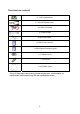
Check the box contents! 1x S5375 motherboard 3 x Serial ATA power cable 6 x Serial ATA Cable 2 x USB2.0 cable 1x Serial Port Cable 1 x S5375 user’s manual 1 x S5375 Quick Reference guide 1 x TYAN driver CD 1 x I/O shield 2 x CPU Back Plane If any of these items are missing, please contact your vendor/dealer for replacement before continuing with the installation process.
NOTE 4
Chapter 1: Introduction 1.1 - Congratulations You have purchased one of the most powerful server solutions. The Tempest ® ® i5100X (S5375) is a flexible Intel platform for multiple applications, based on Intel 5100 MCH and ICH9R chipsets.
Expansion Slots *S5375AG2NR •One (1) PCI-E x16 slot w/ x16 signal •One (1) PCI-E x8 slot w/ x8 signal •Two (2) PCI-X 1.0 64/133 slots •Two (2) 32/33 PCI 2.2 slots (PCI device component height limit = 9.2mm) •Total six slots *S5375G2NR-1U •One (1) PCI-E x16 slot w/ x16 signal •One (1) 32/33 PCI 2.2 slot (PCI device component height limit = 9.2mm) •Total two slots Integrated I/O •Six (6) SATA (3Gb/s) ports •Six (6) USB 2.
Chapter 2: Board Installation You are now ready to install your motherboard. The mounting hole pattern of the Tempest i5100X S5375 matches the SSI CEB specification. Before continuing with installation, confirm that your chassis supports an SSI CEB motherboard. How to install our products right… the first time The first thing you should do is reading this user’s manual. It contains important information that will make configuration and setup much easier.
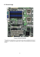
2.1- Board Image Tempest i5100X S5375AG2NR This picture is representative of the latest board revision available at the time of publishing. The board you receive may or may not look exactly like the above picture.
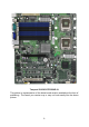
Tempest i5100X S5375G2NR-1U This picture is representative of the latest board revision available at the time of publishing. The board you receive may or may not look exactly like the above picture.
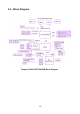
2.
Tempest i5100X S5375G2NR-1U Block Diagram 11
2.3 - Board Parts, Jumpers and Connectors This diagram is representative of the latest board revision available at the time of publishing. The board you receive may not look exactly like the above diagram.
Jumper/Connector Function J2 CD_IN Connector J4 Front Panel Audio Connector J5 AUX_IN Connector J6 IPMB Connector J7 SO-DIMM Socket J10 Chassis Intrusion Connector J11 Fan Board Header for Barebone J12 TYFP2 Connector for Barebone J14 / J15 USB Front Panel Connector J16 Front Panel Header USB1 USB Rear Connector COM2 COM2 Header SATA0~SATA5 Serial ATA Connector PW1 24-pin Power Connector (EPS12V) PW2 8-pin Power Connector (EPS12V) PW3 Aux.
SATA0 SATA1 SATA2 SATA3 SATA4 SATA5 J4 J2 J5 J10 J6 14
J2: CD_IN Connector (S5375AG2NR only) 1 4 Pin Signal Pin Signal 1 3 R GND 2 4 GND L J4: Front Panel Audio Connector (S5375AG2NR only) 2 10 1 9 Pin Signal Pin Signal 1 3 5 7 9 MIC1_LN MIC1_RN FRONT_RN SENSE FRONT_LN 2 4 6 8 10 GND reserved MIC_JD Key LINE_JD J10: Chassis Intrusion Connector Use this header to connect with the front intruder button which indicates the warning message when the system cover is opened.
J15 COM2 J11 J12 16 J14
COM2: COM2 Header Use these pin definitions to connect a port to COM2. *TYAN does not provide cable for this header. It is designed for barebone use only. 2 1 10 Pin Signal Pin Signal 9 1 3 5 7 9 DCD RX TX DTR GND 2 4 6 8 10 DSR RTS CTS RI NC J11: Fan Board Connector for Barebone 13 1 14 2 It is designed for barebone use only.
CPUFAN1 FAN1 CPUFAN2 FAN3 JP5 JP1 FAN2 JP3 J16 JP5: PCI-X Speed Select Jumper (S5375AG2NR only) 1 Pin 1-2 Closed: 133MHz (Default) 3 1 3 Pin 2-3 Closed: 100MHz max.
J16: Front Panel Header The Front Panel Header is used to connect some control or signal wires from motherboard to chassis, such as HDD LED, power LED, power button, and reset button.
2.4 - Tips on Installing Motherboard in Chassis Before installing your motherboard, make sure your chassis has the necessary motherboard support studs installed. These studs are usually metal and are gold in color. Usually, the chassis manufacturer will pre-install the support studs. If you are unsure of stud placement, simply lay the motherboard inside the chassis and align the screw holes of the motherboard to the studs inside the case.
2.5 - Installing the Processor(s) Your Tempest i5100X S5375 supports the latest processor technologies from Intel. Check the TYAN website for latest processor support: http://www.tyan.com Processor Installation (LGA771 Socket) The processor should be installed carefully. Make sure you are wearing an antistatic strap and handle the processor as little as possible. Please note that both processors of the same type and frequency are required for optimal system performance.
3. Lift the metal cover to expose the socket interior and place the socket in as shown. Pin 1 4. Close the cover and return the locking lever to its locked position. 5. Repeat this procedure for the second processor socket. 6. Turn the board upside down and insert the heat sink spring mechanism as shown. 7. Turn the board the right way up again and screw the heat sink into place.
8. Repeat this procedure for the second processor. Cooling Fan Installation After you have installed the processor, the heatsink should be installed to ensure that the processor runs efficiently and does not overheat. Use the heatsink supplied for best results. Follow these instructions to install the heatsink shown. 1. 2. 3. 4. Apply some (a little will work, more doesn’t equal better performance) thermal compound to the top of the processor.
2.6 - Installing the Memory Before installing memory, ensure that the memory you have is compatible with the motherboard and processor. Only DDR2-667/533 DIMM modules are required. Check the TYAN Web site at: www.tyan.com for details of the type of memory recommended for your motherboard. The following diagram shows common types of DDR2 memory modules. Key points to note before installing memory: • Only DDR2-667/533 memory modules are supported.
Memory Installation Procedure Follow these instructions to install memory modules into the Tempest i5100X S5375. 1. Press the locking levers in the direction shown in the following illustration. 2. Align the memory module with the socket. The memory module is keyed to fit only one way in the socket. Key slot 3. Seat the module firmly into the socket by gently pressing down until it sits flush with the socket. The locking levers pop up into place.
2.7 - Attaching Drive Cables Attaching Serial ATA Cables The Tempest i5100X S5375 is also equipped with 6 Serial ATA (SATA) channels. Connections for these drives are also very simple. There is no need to set Master/Slave jumpers on SATA drives. Tyan has supplied two SATA cables and one SATA power adapter. If you are in need of other cables or power adapters please contact your place of purchase. The following pictures illustrate how to connect an SATA drive 1.SATA drive cable connection 2.
2.8 - Installing Add-In Cards Before installing add-in cards, it’s helpful to know if they are fully compatible with your motherboard. For this reason, we’ve provided the diagrams below, showing the slots that appear on your motherboard. PCI-E x16 slot (w/ x16 bus) PCI 32/33MHz slot PCI-E x8 slot (w/ x8 bus) PCI-X 64/133MHz slots PCI 32/33MHz slot Simply find the appropriate slot for your add-in card and insert the card firmly. Do not force any add-in cards into any slots if they do not seat in place.
2.9 - Installing Optional SO-DIMM modules Your S5375 motherboard is equipped with an optional proprietary SO-DIMM connector. The 200-pin vertical SO-DIMM connector can be used for TYAN M32952/M3296 expansion card to provide such features as additional TYAN SMDC module support. For details of available expansions cards, visit the TYAN website at http://www.tyan.com. To install a SO-DIMM expansion card: 1. Open the spring levers as shown. 2.
2.10 - Connecting External Devices The following diagrams will detail the rear port stack for this S5375 motherboard: PS/2 Mouse/Keyboard LAN Ports IPMI LAN Port USB x 2 VGA Port Serial Port NOTE: Peripheral devices can be plugged straight into any of these ports but software may be required to complete the installation. Onboard LAN LED Color Definition The three onboard Ethernet ports have green and yellow LEDs to indicate LAN status. The chart below illustrates the different LED states.
2.11 - Installing the Power Supply There are two power connectors on your Tempest i5100X S5375. The Tempest i5100X S5375 requires 2 power inputs. - 24-pin (PW1) - 8-pin (PW2) NOTE: Please be aware that ATX 2.x, ATX12V and ATXGES power supplies may not be compatible with the board and can damage the motherboard and/or CPU(s). 1 x 24-pin 12V Power Connector 1 x 8-pin 12V Power Connector 1 x 4-pin 12V/5V Power Connector (PW3, aux. power supply for TYAN Riser Card M2061) Applying power to the board: 1.
Chapter 3: BIOS Setup About the BIOS The BIOS is the basic input/output system, the firmware on the motherboard that enables your hardware to interface with your software. The BIOS determines what a computer can do without accessing programs from a disk. The BIOS contains all the code required to control the keyboard, display screen, disk drives, serial communications, and a number of miscellaneous functions. This chapter describes the various BIOS settings that can be used to configure your system.
Setup Basics The table below shows how to navigate in the setup program using the keyboard.
3.1 BIOS Main Menu The Main BIOS Menu is the first screen that you can navigate. The Main BIOS setup menu screen has two main frames. The left frame displays all the options that can be configured. "Grayed-out" options cannot be configured, options in blue can be changed. The right frame displays the key legend. Above the key legend is an area reserved for a text message. When an option is selected in the left frame, it is highlighted in white. Often, a text message will accompany it.
3.2 Advanced Menu You can select any of the items in the left frame of the screen, such as Super I/O Configuration, to go to the sub menu for that item. You can display an Advanced BIOS Setup option by highlighting it using the keys. All Advanced BIOS Setup options are described in this section. The Advanced BIOS Setup screen is shown below. The sub menus are described on the following pages.
3.2.1 CPU Configuration You can use this screen to view CPU Configuration Menu. Use the up and down arrow (Ç/È) keys to select an item. Use the Plus and Minus (+/-) keys to change the value of the selected option. The settings are described on the following pages. Main Advanced BIOS Setup Utility PCI/PnP Boot Security Chipset Exit Configure advanced CPU settings Module Version: 3F.00 Manufacturer: Intel Intel ® Xeon ® CPU: 5130 @2.00GHz Frequency: 1.
C1E Support Enabled Disabled Enabled Hardware Prefetcher Disabled Enabled Adjacent Cache Line Prefetch Disabled Enabled Max CPUID Value Limit Disabled Enabled Virtualization Technology Disabled Enabled Execute-Disable Bit Capability Disabled 36 Enable or disable the C1 Enhanced mode When enabled, the processor's hardware prefetcher will be enabled and allowed to automatically prefetch data and code for the processor. When disabled, the processor's hardware prefetcher will be disabled.
Enabled PECI Disabled Core Multi-Processing Enabled Disabled Enabled Intel® SpeedStep™ Tech Disabled 37 Enable/disable the Platform Environment Control Interface (PECI). Enabled: CPU supports PECI When disabled, it disables one execution core. Enhanced Intel SpeedStep technology allows the system to dynamically adjust processor voltage and core frequency, which can result in decreased average power consumption and decreased average heat production.
3.2.2 IDE Configuration Sub-Menu You can use this screen to select options for the IDE Configuration Settings. Use the up and down keys to select an item. Use the and keys to change the value of the selected option.
3.2.2.1 SATA0 ~ SATA5 Sub-Menu Main SATA0 Advanced BIOS Setup Utility PCI/PnP Boot Security Device: Not Detected [Auto] [Auto] [Auto] [Auto] [Auto] [Auto] [Enabled] Type LBA /Large Mode Block (Multi-Sector Transfer) PIO Mode DMA Mode S.M.A.R.T.
3.2.3 Super IO Configuration Sub-Menu You can use this screen to select options for the Super I/O settings. Use the up and down arrow (Ç/È) keys to select an item.
3.2.4 USB Configuration Sub-Menu You can use this screen to view the USB Configuration Menu. Use the up and down arrow (Ç/È) keys to select an item. Use the Plus and Minus (+/-) keys to change the value of the selected option. The settings are described on the following pages. Main Advanced BIOS Setup Utility PCI/PnP Boot Security Chipset Exit Enables support for legacy USB. AUTO option disables legacy support if no USB devices are connected. USB Configuration Module Version – x.xx.x – xx.
3.2.4.
3.2.5 ACPI Configuration Sub-Menu Use this screen to select options for ACPI. Use the up and down arrow (Ç/È) keys to select an item. Use the Plus and Minus (+/-) keys to change the value of the selected option. A description of the selected item appears on the right side of the screen. The settings are described on this page. The screen is shown below.
3.2.5.1 Advanced ACPI Configuration Sub-Menu Main Advanced BIOS Setup Utility PCI/PnP Boot Security Chipset Exit Advanced ACPI Configuration ACPI Version Features ACPI APIC support AMI OEMB table Headless mode Feature Advanced ACPI Configuration [ACPI v3.0] [Enabled] [Enabled] [Disabled] Option ACPI v3.0 ACPI Version Features ACPI v2.0 ACPI v1.
3.2.5.
3.2.6 AHCI Configuration Sub-Menu You can use this screen to view the AHCI Configuration Menu. Use the up and down arrow (Ç/È) keys to select an item. Use the Plus and Minus (+/-) keys to change the value of the selected option. The settings are described on the following pages.
3.2.6.1 AHCI Port0/Port1/Port2/Port3/Port4/Port5 Sub-Menu Main Advanced BIOS Setup Utility PCI/PnP Boot Security Chipset Exit AHCI Port0 Device: Not Detected SATA Port0 S.M.A.R.T. Feature AHCI Port0 Configuration SATA Port0 [Auto] [Enabled] Option Auto Not Installed Enabled S.M.A.R.T. Disabled 47 ← → Select Screen ↑↓ Select Item +/- Change Option F1 General Help F10 Save and Exit ESC Exit Description Select the type of device connected to the system. S.M.A.R.
3.2.7 APM Configuration Main Advanced BIOS Setup Utility PCI/PnP Boot Security Power Management/APM Video Power Down Mode Hard Disk Power Down Mode Suspend Time Out Throttle Slow Clock Ratio Keyboard & PS/2 Mouse [Enabled] [Suspend] [Suspend] [Disabled] [50%] [MONITOR] Power Button Mode [On/Off] Advanced Resume Event Control Resume On Ring Resume On RTC Alarm [Disabled] [Disabled] Power Management/APM Video Power Down Mode Hard Disk Power Down Mode Suspend Time Out Exit Enable or disable APM.
Throttle Slow Clock Ratio Keyboard & PS/2 Mouse Power Button Mode Resume On Ring Resume On RTC Alarm 87.5% 75.0% 62.5% 50% 37.5% 25% 12.5% Select the duty cycle in throttle mode MONITOR Ignore On/Off Monitor KBC Ports 60/64 Go into On/Off, or Suspend when Power Button is pressed.
3.2.8 Event Log Configuration Sub-Menu You can use this screen to view the Event Log Control Menu. This logs system events (such as CMOS clear) and writes the log into NVRAM. Use the up and down arrow (Ç/È) keys to select an item. Use the Plus and Minus (+/-) keys to change the value of the selected option. The settings are described on the following pages.
3.2.9 Hardware Health Configuration Sub-Menu You can use this screen to view the Hardware Health Configuration Settings. Use the up and down arrow (Ç/È) keys to select an item. Use the Plus and Minus (+/-) keys to change the value of the selected option. The settings are described on the following pages.
3.2.9.1 Mainboard Voltages Report Sub-Menu Main Advanced BIOS Setup Utility PCI/PnP Boot Security Chipset Exit Board Voltages Event Monitoring CPU0 Vcore CPU1 Vcore 12V 3.3Vsb -12V VBat Vdimm 1.5V 5V : x.xxx V : x.xxx V : x.xxx V : x.xxx V : x.xxx V : x.xxx V : x.xxx V : x.xxx V : x.xxx V Read only. It can not be modified in user mode.
3.2.10 Remote Access Configuration Sub-Menu You can use this screen to view the Remote Access Configuration Menu. This feature allows access to the Server remotely via serial port. Use the up and down arrow (Ç/È) keys to select an item. Use the Plus and Minus (+/-) keys to change the value of the selected option. The settings are described on the following pages.
None Flow Control Hardware Select Flow Control for console redirection. Software Disabled Redirection After BIOS POST Boot Loader Always Disable: Turns off the redirection after POST Boot Loader: Redirection is active during POST and during Boot Loader. Always: Redirection is always active. ANSI Terminal Type Select the target terminal type.
3.3 PCI PnP Menu You can use this screen to view PnP (Plug & Play) BIOS Configuration Menu. This menu allows the user to configure how the BIOS assigns resources & resolves conflicts. Use the up and down arrow (Ç/È) keys to select an item. Use the Plus and Minus (+/-) keys to change the value of the selected option. The settings are described on the following pages. Main Advanced BIOS Setup Utility PCI/PnP Boot Security Chipset Exit Clear NVRAM during System Boot.
Allocate IRQ to PCI VGA Yes Yes: assigns IRQ to PCI VGA card if card requests IRQ. No Disabled Palette Snooping Enabled Disabled PCI IDE BusMaster Enabled 56 This is the default setting and should not be changed unless the VGA card manufacturer requires Palette Snooping to be Enabled. Enabled: informs the PCI devices that an ISA graphics device is installed in the system so the card will function correctly. Enabled: BIOS uses PCI bus mastering for reading / writing to IDE drives.
3.4 Boot Menu You can display Boot Setup option by highlighting it using the Arrow (Ç/È) keys and pressing Enter. The settings are described on the following pages. Main Advanced BIOS Setup Utility PCI/PnP Boot Security Chipset Exit Configures settings during System Boot. Boot Settings Boot Settings Configuration ← → Select Screen ↑↓ Select Item Enter Go to Sub Screen F1 General Help F10 Save and Exit ESC Exit Boot Device Priority Removable Drives 3.4.
Feature Option Description Boot Settings Configuration Quick Boot Quiet Boot Enabled This option allows user bypass BIOS self test during POST. Disabled Disabled Enabled Add On ROM Display Mode Bootup Num-Lock Force BIOS Keep Current On Off Disabled: displays normal POST messages. Enabled: displays OEM log instead of POST messages. Allows user to force BIOS/Option ROM of add-on cards to be displayed during quiet boot. Selects Power-on state for Numlock.
3.4.2 Boot Device Priority Use this screen to select options for the Boot Device Priority. Use the up and down arrow (Ç/È) keys to select an item. Use the Plus and Minus (+/-) keys to change the value of the selected option. Main Advanced BIOS Setup Utility PCI/PnP Boot Security Boot Device Priority 1st Boot Device 2nd Boot Device 3rd Boot Device [xx,xxx-xxxxx:xxx] [xx,xxx-xxxxx:xxx] [xx,xxx-xxxxx:xxx] Chipset Exit Specifies the boot sequence from the available devices.
3.4.3 Removable Drives Use this screen to select options for the Removable Drives. Use the up and down arrow (Ç/È) keys to select an item. Use the Plus and Minus (+/-) keys to change the value of the selected option. Main Advanced BIOS Setup Utility PCI/PnP Boot Security Removable Drives 1st Drive [xxxxxxxx] Chipset Exit Specifies the boot sequence from the available devices.
3.5 Security Menu The system can be configured so that all users must enter a password every time the system boots or when BIOS Setup is entered, using either the Supervisor password or User password. The Supervisor and User passwords activate two different levels of password security. If you select password support, you are prompted for a one to six character password. Type the password on the keyboard. The password does not appear on the screen when typed. Make sure you write it down.
3.6 Chipset Menu This menu allows the user to customize functions of the AMD Chipsets. North Bridge configuration contains options for Memory & CPU settings. Select a menu by highlighting it using the Arrow (Ç/È) keys and pressing Enter. The settings are described on the following pages. Main Advanced BIOS Setup Utility PCI/PnP Boot Security Chipset Exit Advanced Chipset Settings Options for NB WARNING: Setting wrong values in below sections may cause system to malfunction.
3.6.1 North Bridge Configuration Sub-Menu This menu gives options for customizing North Bridge Chipset settings. Select a menu by highlighting it using the Arrow (Ç/È) keys and pressing Enter. The settings are described on the following pages.
Feature Option North Bridge Chipset Configuration Channel Dependent Sparing Channel 0 Channel Specific Sparing Rank Interleaving Channel 1 Channel Specific Sparing Rank Interleaving Boots Graphic Adapter Priority Description Enabled Channel dependent rank/DIMM sparing enabled/disabled Disabled Enabled Channel 0 enabled/disabled Disabled Disabled Enables rank/DIMM sparing feature Enabled 1:1 2:1 4:1 Rank Interleaving setting Enabled Channel 1 enabled/disabled Disabled Disabled Enables rank/DIMM
3.6.2 South Bridge Configuration Sub-Menu This menu gives options for customizing South Bridge Chipset settings. Select a menu by highlighting it using the Arrow (Ç/È) keys and pressing Enter. The settings are described on the following pages. Main Advanced BIOS Setup Utility PCI/PnP Boot Security Chipset Exit South Bridge Chipset Configuration HDA Controller SMBUS Controller [Enabled] [Enabled] SLP_S4# Min.
3.7 Exit Menu You can display an Exit BIOS Setup option by highlighting it Arrow (Ç/È) keys and pressing Enter. Main Advanced BIOS Setup Utility PCI/PnP Boot Security Chipset Exit Exit Options Exit system setup after saving the changes. Save Changes and Exit Discard Changes and Exit Discard Charges F10 key can be used for this operation.
Chapter 4: Diagnostics NOTE: if you experience problems with setting up your system, always check the following things in the following order: Memory, Video, CPU By checking these items, you will most likely find out what the problem might have been when setting up your system. For more information on troubleshooting, check the TYAN website at: http://www.tyan.com. 4.1 Beep Codes Fatal errors, which halt the boot process, are communicated through two kinds of audible beeps.
4.3 AMIBIOS Post Code The POST code checkpoints are the largest set of checkpoints during the BIOS preboot process. The following table describes the type of checkpoints that may occur during the POST portion of the BIOS: Checkpoint 03 04 05 06 08 0A 0B 0C 0E 13 24 30 2A 2C 2E 31 33 37 Description Disable NMI, Parity, video for EGA, and DMA controllers. Initialize BIOS, POST, Runtime data area. Also initialize BIOS modules on POST entry and GPNV area.
Checkpoint 38 39 3A 3B 3C 40 50 52 60 75 78 7A 7C 84 85 87 8C 8E 90 A0 A1 A2 A4 A7 A8 A9 AA AB AC B1 00 Description Initializes different devices through DIM. See DIM Code Checkpoints section of document for more information. Initializes DMAC-1 & DMAC-2. Initialize RTC date/time. Test for total memory installed in the system. Also, Check for DEL or ESC keys to limit memory test. Display total memory in the system. Mid POST initialization of chipset registers.
NOTE 70
Appendix: SMDC Information Overview Tyan Server Management Daughter Card (SMDC) is a powerful yet cost-efficient solution for high-end server management hardware packages. Tyan’s goal is to provide remote system monitoring and control even when the operating system is absence or simply fails. This empowers Tyan’s server board with advanced industrial-standard features. Tyan SMDC is a snap-in card that provides essential server management solution.
Features of Tyan Server Management Monitor various system components remotely - such as fans, processor temperature, and more Remote power on and power off Console redirect -the ability to view system remotely Alert and error actions -such as audible beep, e-mail, power down and reboot SMDC runs on stand-by power -the SMDC will continue to function, even if the system is not powered on How SMDC and TSO Work The brief descriptions below will help explain how these items function.
Glossary ACPI (Advanced Configuration and Power Interface): a power management specification that allows the operating system to control the amount of power distributed to the computer’s devices. Devices not in use can be turned off, reducing unnecessary power expenditure. AGP (Accelerated Graphics Port): a PCI-based interface which was designed specifically for demands of 3D graphics applications. The 32-bit AGP channel directly links the graphics controller to the main memory.
Bus: a data pathway. The term is used especially to refer to the connection between the processor and system memory, and between the processor and PCI or ISA local buses. Bus mastering: allows peripheral devices and IDEs to access the system memory without going through the CPU (similar to DMA channels). Cache: a temporary storage area for data that will be needed often by an application. Using a cache lowers data access times, since the needed information is stored in the SRAM instead of in the slow DRAM.
Doze mode: in this mode, only the CPU’s speed is slowed. DRAM (Dynamic RAM): widely available, very affordable form of RAM which has the unfortunate tendency to lose data if it is not recharged regularly (every few milliseconds). This refresh requirement makes DRAM three to ten times slower than non-recharged RAM such as SRAM. ECC (Error Correction Code or Error Checking and Correcting): allows data to be checked for errors during run-time.
Initial Program Load (IPL): a feature built into BBS-compliant devices, describing those devices as capable of loading and executing an OS, as well as being able to provide control back to the BIOS if the loading attempt fails. IPL: see Initial Program Load. IRQ (Interrupt Request): an electronic request that runs from a hardware device to the CPU. The interrupt controller assigns priorities to incoming requests and delivers them to the CPU.
PnP (Plug-n-Play): a design standard that has become ascendant in the industry. Plug-n-Play devices require little set-up to use. Novice end users can simply plug them into a computer that is running on a Plug-n-Play aware operating system (such as Windows 98), and go to work. Devices and operating systems that are not Plug-n-Play require you to reconfigure your system each time you add or change any part of your hardware.
Serial port: called as such because it transmits the eight bits of a byte of data along one wire, and receives data on another single wire (that is, the data is transmitted in serial form, one bit after another). SIMM (Single In-line Memory Module): formally the most common form of RAM for motherboards. They must be installed in pairs, and do not have the carrying capacity or the speed of DIMM modules. Sleep/Suspend mode: in this mode, all devices except the CPU shut down.
Technical Support If a problem arises with your system, you should turn to your dealer for help first. Your system has most likely been configured by them, and they should have the best idea of what hardware and software your system contains. Furthermore, if you purchased your system from a dealer near you, you can bring your system to them to have it serviced instead of attempting to do so yourself (which can have expensive consequences). Help Resources: 1. See the beep codes section of this manual. 2.
Notice for the USA Compliance Information Statement (Declaration of Conformity Procedure) DoC FCC Part 15: This device complies with part 15 of the FCC Rules Operation is subject to the following conditions: This device may not cause harmful interference, and This device must accept any interference received including interference that may cause undesired operation.