Tempest i5000PX /// S5380 Version 1.1 Copyright Copyright © TYAN Computer Corporation, 2006. All rights reserved. No part of this manual may be reproduced or translated without prior written consent from TYAN Computer Corp. Trademark All registered and unregistered trademarks and company names contained in this manual are property of their respective owners including, but not limited to the following. TYAN, Tempest i5000PX are trademarks of TYAN Computer Corporation.
Table of Contents Check the box contents! Chapter 1: Introduction 1.1 Congratulations…………………………………………………………… 1.2 Hardware Specifications………………………………………………… Chapter 2: Board Installation 2.1 Board Image……………………………………………………………… 2.2 Block Diagram……………………………………………………………. 2.3 Board Parts, Jumpers and Connectors………………………………... 2.4 Tips on Installing Motherboard in Chassis…………………………….. 2.5 Installing the Processor(s)………………………………....................... 2.6 Installing the Memory……………………………………………………. 2.
Check the box contents! 1x S5380 motherboard 1x 34-Pin floppy drive cable 1 x Ultra-DMA-133/100/66/33 IDE cable 3 x Serial ATA power cable 6 x Serial ATA Cable 1 x COM Port Cable 1 x S5380 user’s manual 1 x S5380 Quick Reference guide 1 x TYAN driver CD 1 x I/O shield 2 x CPU Back Plane If any of these items are missing, please contact your vendor/dealer for replacement before continuing with the installation process.
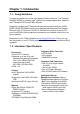
Chapter 1: Introduction 1.1 - Congratulations You have purchased one of the most powerful server solutions. The Tempest i5000PX (S5380) is a flexible Intel® platform for multiple applications, based on ® Intel “Blackford” MCH and ESB2 chipsets.
BIOS •Phoenix BIOS on 8Mbit Flash ROM •Support APM 1.2, ACPI 1.0b •Serial Console Redirect •PXE via Ethernet, USB device boot •PnP, DMI 2.0, WFW 2.
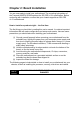
Chapter 2: Board Installation You are now ready to install your motherboard. The mounting hole pattern of the Tempest i5000PX S5380 matches the SSI CEB v1.01 specification. Before continuing with installation, confirm that your chassis supports an SSI CEB v1.01 motherboard. How to install our products right… the first time The first thing you should do is reading this user’s manual. It contains important information that will make configuration and setup much easier.
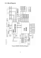
2.1- Board Image This picture is representative of the latest board revision available at the time of publishing. The board you receive may or may not look exactly like the above picture.
2.
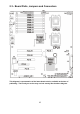
2.3 - Board Parts, Jumpers and Connectors This diagram is representative of the latest board revision available at the time of publishing. The board you receive may not look exactly like the above diagram.
Jumper Legend OPEN - Jumper OFF, without jumper cover CLOSED – Jumper ON, with jumper cover Jumper/Connector Function J8 Onboard VGA Jumper - Open: Enable VGA (Default) - Closed: Disable VGA J25 COM2 Header J27 Fan Connector (for barebone use only) J28 IPMB Connector J7/J44/J68 Chassis Fan Connectors J7: FAN1, J44: FAN3, J68: FAN2 J39/J40 CPU Fan Connectors J39: CPUFAN1 J40:CPUFAN0 J70 Chassis LCD Module Interface Header J76 IDE Connector J74 The 2nd Front Panel Header J77 The
J8 USB1 USB2 12 J28
USB1/USB2: Front Panel USB2.0 Connector 1 Pin 1 USB PWR Pin 2 USB_N_FB Pin 3 USB_P_FB Pin 4 GND Use these headers to connect to the USB devices. J8: Onboard VGA Jumper Enable the onboard ATI VGA function.
J47 J25 14 J74
JP47: Clear CMOS Jumper 3 Use this jumper when you forgot your system/setup password or need to clear system BIOS setting. 1 Normal (Default) 3 1 Clear How to clear the CMOS data Power off system and disconnect power supply from AC source Use jumper cap to close Pin_2 and 3 for several seconds to Clear CMOS Replace jumper cap to close Pin_1 and 2 Reconnect power supply to AC source Power on system J25: COM2 Header 2 10 1 9 Use these pin definitions to connect a port to COM2.
J79 J70 J27 J27: FAN Connector (for barebone use only) Use these pin definitions to connect to the barebone fans.
J70: LCM Module Header 2 1 6 5 Signal Pin Pin +5V 1 2 Signal SIN Key 3 4 GND +5Vsb 5 6 SOUT Use this header to connect the LCM module with system monitoring function. This header is reserved for barebone use. J79: SMDC Connector The SMDC connector allows you to connect with Tyan Server Management Daughter Card (SMDC). The S5380 supports Tyan SMDC M3291. See Appendix I for more information on SMDC.
J40 J39 J7 J68 J44 SATA 0/1/2/3/4/5 18
J39/J40: CPU0/CPU1 Fan Connectors G ND 12V Tac homet er P WM Use this header to connect the processor cooling fan to your motherboard to keep the system at optimum performance levels. J39: CPUFAN1; J40: CPUFAN0 J68: Chassis Fan Connector G ND 12V Tac homet er P WM Use this header to connect the chassis cooling fan to your motherboard to keep the system at optimum performance levels.
2.4 - Tips on Installing Motherboard in Chassis Before installing your motherboard, make sure your chassis has the necessary motherboard support studs installed. These studs are usually metal and are gold in color. Usually, the chassis manufacturer will pre-install the support studs. If you are unsure of stud placement, simply lay the motherboard inside the chassis and align the screw holes of the motherboard to the studs inside the case.
2.5 - Installing the Processor(s) Your Tempest i5000PX S5380 supports the latest processor technologies from Intel. Check the TYAN website for latest processor support: http://www.tyan.com Processor Installation The processor should be installed carefully. Make sure you are wearing an antistatic strap and handle the processor as little as possible. Follow these instructions to install your processor 1. Locate the processor socket on the motherboard and lift the protective cover off as shown.
3. Lift the metal cover to expose the socket interior and place the socket in as shown. Pin 1 4. Close the cover and return the locking lever to its locked position. 5. Repeat this procedure for the second processor socket. 6. Turn the board upside down and insert the heat sink spring mechanism as shown.
7. Turn the board the right way up again and screw the heat sink into place. 8. Repeat this procedure for the second processor. Cooling Fan Installation After you have installed the processor, the heatsink should be installed to ensure that the processor runs efficiently and does not overheat. Use the heatsink supplied for best results. Follow these instructions to install the heatsink shown. 1. 2. 3. 4.
2.6 - Installing the Memory Before installing memory, ensure that the memory you have is compatible with the motherboard and processor. Only DDR2-667/533 Fully Buffer DIMM (FB DIMM) modules are required. Check the TYAN Web site at: www.tyan.com for details of the type of memory recommended for your motherboard. The following diagram shows common types of FB-DIMM memory modules. Key points to note before installing memory: • • Only DDR2 667/533 FB-DIMM memory modules are supported.
Memory Installation Procedure Follow these instructions to install memory modules into the Tempest i5000PX S5380. 1. Press the locking levers in the direction shown in the following illustration. 2. Align the memory module with the socket. The memory module is keyed to fit only one way in the socket. Key slot 3. Seat the module firmly into the socket by gently pressing down until it sits flush with the socket. The locking levers pop up into place.
2.7 - Attaching Drive Cables Attaching IDE Drive Cable Attaching the IDE drive cable is simple. These cables are “keyed” to only allow them to be connected in the correct manner. TYAN motherboards have two on-board IDE channels, each supporting two drives. The black connector designates the Primary channel, while the white connector designates the Secondary channel.
Tyan has supplied two SATA cables and one SATA power adapter. If you are in need of other cables or power adapters please contact your place of purchase. The following pictures illustrate how to connect an SATA drive 1.SATA drive cable connection 2. SATA drive power connection 3. SATA cable motherboard connector 4. SATA drive power adapter Attaching Floppy Drive Cables Attaching floppy diskette drives are done in a similar manner to hard drives. See the picture below for an example of a floppy cable.
2.8 - Installing Add-In Cards Before installing add-in cards, it’s helpful to know if they are fully compatible with your motherboard. For this reason, we’ve provided the diagrams below, showing the slots that appear on your motherboard. PC I-X (64 /133) PC I Expr es s (x4) PC I Expr es s (x16 ) PC I Expr es s (x8) Simply find the appropriate slot for your add-in card and insert the card firmly. Do not force any add-in cards into any slots if they do not seat in place.
2.9 - Connecting External Devices The following diagrams will detail the rear port stack for this S5380 motherboard: LAN Port (10/100/1000) x2 + USB x 4 PS/2 Mouse/Keyboard USB x 2 VGA Port Serial Port NOTE: Peripheral devices can be plugged straight into any of these ports but software may be required to complete the installation. Onboard LAN LED Color Definition The three onboard Ethernet ports have green and yellow LEDs to indicate LAN status. The chart below illustrates the different LED states.
2.10 - Installing the Power Supply There are three power connectors on your Tempest i5000PX S5380. The Tempest i5000PX S5380 requires that you have an EPS12V power supply that has a 24-pin, an 8-pin and a 4-pin power connectors. Except the 24-pin and 8pin power supplies, you also need to connect a 4-pin power supply for the power of South Bridge. NOTE: Please be aware that ATX 2.x, ATX12V and ATXGES power supplies may not be compatible with the board and can damage the motherboard and/or CPU(s).
Chapter 3: BIOS Setup 3.1. About the BIOS The BIOS is the basic input/output system, the firmware on the motherboard that enables your hardware to interface with your software. The BIOS determines what a computer can do without accessing programs from a disk. The BIOS contains all the code required to control the keyboard, display screen, disk drives, serial communications, and a number of miscellaneous functions. This chapter describes the various BIOS settings that can be used to configure your system.
3.1.3 In Case of Problems If you have trouble booting your computer after making and saving the changes with the BIOS setup program, you can restart the computer by holding the power button down until the computer shuts off (usually within 4 seconds); resetting by pressing CTRL-ALT-DEL; or clearing the CMOS. The best advice is to only alter settings that you thoroughly understand. In particular, do not change settings in the Chipset section unless you are absolutely sure of what you are doing.
3.2 BIOS Main Menu In this section, you can alter general features such as the date and time, as well as access to the IDE configuration options. Note that the options listed below are for options that can directly be changed within the Main Setup screen. Main Advanced PhoenixBIOS Setup Utility Security Power System Time: System Date: BIOS Version: BIOS Build Date: [xx:xx:xx] [xxxx-xx-xx] Legacy Diskette A: [1.44/1.
Legacy Diskette A Defines the floppy drive type NONE / 360K, 5.25 in / 1.2 M, 5.25 in / 720 K, 3.5 in / 1.44 M, 3.5 in / 2.88 M, 3.5 in System Memory This display allows you to change the amount of system memory present on the system. Extended Memory This displays/allows you to change the amount of extended memory present on the system.
3.2.1 IDE Primary/Secondary Master/Slave Setup Computer detects IDE drive type from drive C to drive F. Press Enter on any of the Primary/Master, Primary/Slave, Secondary/Master, Secondary/Slave options to view advanced details of the corresponding drive. The system displays advanced details like the number of heads/cylinders/sectors on the detected disk and the maximum storage capacity of the disk.
large mode, or it may be done using a different algorithm called LBA-assist translation. The translated geometry is still what is presented to the operating system for use in Int 13h calls. The difference between LBA and ECHS is that when using ECHS the BIOS translates the parameters used by these calls from the translated geometry to the drive's logical geometry. With LBA, it translates from the translated geometry directly into a logical block (sector) number.
3.2.2 Memory Cache This setting allows you to tweak the various cache settings for optimal performance of your system. Press Enter to display the various cache settings.
As such, it would be a waste of L2 cache bandwidth to cache the video BIOS instead of data that are more critical to the system's performance. In addition, if any program writes into this memory area, it will result in a system crash. So, it is recommended that you write protect this area for optimal system performance. Uncached / Write Protect Cache Base 0-512K This feature allows you to control caching of 512K base memory.
3.2.3 Boot Features This option allows setting boot parameters. Press Enter to view the Boot Features screen.
Quick Boot Mode This BIOS feature allows you to decrease the time it takes to boot up the computer by shortening or skipping certain standard booting procedures. If enabled, the BIOS will shorten the booting process by skipping some tests and shortening others.
3.3 Advanced Menu This section facilitates configuring advanced BIOS options for your system.
Please note that the BIOS will automatically reset it to the default setting of No after reconfiguring the new ESCD. So, there is no need for you to manually disable this feature after rebooting. Yes / No Large Disk Access Mode This option determines whether a hard drive with more than 1024 cylinders, more than 16 heads and or more than 64 tracks per sector is present on the system. Set this option to DOS if such a hard drive is present. Else, set this option to Other.
3.3.1 Advanced Chipset Control This section allows you to fine tune the chipset configuration.
Memory Branch Mode This option is used to select the type of memory operation mode. Interleave / Sequential / Mirror Branch 0/1 Rank Sparing This option is used to enable/disable Branch 0/1 rank/DIMM sparing feature. Enabled / Disabled Enhanced x8 Detection This feature is used to enable/disable enhanced x8 DRAM UC error detection. Enabled / Disabled Watchdog Timer This feature allows you to enable watchdog timer.
3.3.1.1 ICH USB Control Sub-Menu These items are used to control the various ICH USB devices.
3.3.1.2 Lan Control Sub-Menu These items allow you to control the LAN devices. Main PhoenixBIOS Setup Utility Advanced Security Power LAN Control Sub Menu LAN1 (Gilgal) Option ROM Scan [Enabled] [Disabled] LAN2 (Gilgal) Option ROM Scan [Enabled] [Disabled] F1 Help Esc Exit ↑↓ Select Item ← → Select Menu Boot -/+ Change Values Enter Select X Sub-Menu F9 Setup Defaults F10 Previous Values LAN1 Gilgal/LAN2 Gilgal This feature is used to enable/disable the integrated LAN interface.
3.3.2 Advanced Processor Options This section allows you to fine-tune the processor options.
Intel® Virtualization Technology This feature is used to configure the Intel Virtualization technology. Disabled / Enabled Machine Checking This feature is used to enable the function of machine checking. Enabled / Disabled C1 Enhanced Mode This feature is used to enable the C1 Enhanced mode. Enabled / Disabled Thermal Management 2 This feature is used to enable the function of Thermal Management 2.
3.3.3 I/O Device Configuration This setting allows you to configure I/O devices.
3.3.4 Hardware Monitor Configuration This displays critical system parameters like CPU speed, fan speeds, voltage levels and CPU temperature. PhoenixBIOS Setup Utility Advanced Security Power Hardware Monitor Main XVoltage Boot Exit Item Specific Help Monitoring Cpu0 Fan Cpu1 Fan Fan1 Fan2 Fan3 Cpu0 Temp. System Temp.
3.3.4.1 Voltage Monitoring Sub-Menu PhoenixBIOS Setup Utility Advanced Security Power Voltage Monitoring Main Boot Exit Item Specific Help 3.
3.3.
3.3.6 Console Redirection Main PhoenixBIOS Setup Utility Advanced Security Power Console Redirection Com Port Address [Disabled] Baud Rate Console Type Flow Control Console connection: Continue C.R. after POST: [19.2K] [VT100] [None] [Direct] [Off] F1 Help Esc Exit ↑↓ Select Item ← → Select Menu Boot Exit Item Specific Help -/+ Change Values Enter Select X Sub-Menu F9 Setup Defaults F10 Previous Values Com Port Address If enabled it will use a port on the motherboard.
3.4 Security These settings allow you to configure the security options for your system. Main Advanced PhoenixBIOS Setup Utility Security Power Set Supervisor Password Set User Password [Enter] [Enter] Password on boot: [Disabled] ↑↓ Select Item ← → Select Menu Exit Item Specific Help Supervisor Password Is: User Password Is: F1 Help Esc Exit Boot -/+ Change Values Enter Select X Sub-Menu F9 Setup Defaults F10 Previous Values The system displays the current supervisor and user passwords.
3.5 Power These settings allow you to configure the power options for your system.
3.6 Boot Menu Use this screen to select options for the Boot Settings Configuration. Main Advanced PhoenixBIOS Setup Utility Security Power ↑↓ Select Item ← → Select Menu Exit Item Specific Help Keys used to view or configure devices: expands or collapses devices with a + or – expands all enables or disables a device. <+> and <-> moves the device up or down. May move removable device between Hard Disk or Removable Disk. Remove a device that is not installed.
3.7 Exit Menu These settings set the exit options on your system. Main Advanced PhoenixBIOS Setup Utility Security Power ↑↓ Select Item ← → Select Menu Exit Item Specific Help Exit system Setup and save your changes to CMOS. Exit Saving Changes Exit Discarding Changes Load Setup Defaults Discard Changes Save Changes F1 Help Esc Exit Boot -/+ Change Values Enter Select X Sub-Menu Exit Saving Changes This exits BIOS setup after saving the changes made.
NOTE 58
Chapter 4: Diagnostics NOTE: If you experience problems with setting up your system, always check the following things in the following order: Memory, Video, CPU By checking these items, you will most likely find out what the problem might have been when setting up your system. For more information on troubleshooting, check the TYAN website at: http://www.tyan.com. 4.1 Beep Codes Fatal errors, which halt the boot process, are communicated through two kinds of audible beeps.
4.
30h 6Ah 6Bh 6Ch 6Eh 70h 72h 76h 7Ch 7Eh 80h 81h 82h 83h 84h 85h 86h. 87h 88h 89h 8Ah 8Bh 8Ch 8Fh 90h 91h 92h 93h 95h 96h system BIOS shadow 1-4-1-1.
97h 98h A0h E9h EAh EBh Fixup Multi Processor table 1-2. Search for option ROMs.
Appendix I: SMDC Information Overview Tyan Server Management Daughter Card (SMDC) is a powerful yet cost-efficient solution for high-end server management hardware packages. Tyan’s goal is to provide remote system monitoring and control even when the operating system is absence or simply fails. This empowers Tyan’s server board with advanced industrial-standard features. Tyan SMDC is a snap-in card that provides essential server management solution.
Features of Tyan Server Management Monitor various system components remotely - such as fans, processor temperature, and more Remote power on and power off Console redirect -the ability to view system remotely Alert and error actions -such as audible beep, e-mail, power down and reboot SMDC runs on stand-by power -the SMDC will continue to function, even if the system is not powered on How SMDC and TSO Work The brief descriptions below will help explain how these items function.
Appendix II: How to Make a Driver Diskette Follow the steps below to make a driver diskette from the TYAN driver CD provided. 1. Start the system and insert the TYAN CD into the CD-ROM drive to boot from CD. You will see the following menu. Then press [1] and [Enter] to boot the system to Tyan diskette maker. (If you would like to boot from hard disk, press 0 and Enter or just wait for 10 seconds to boot automatically from hard disk.). Boot from CD: ISOLINUX 2.00 2002-10-25 Copyright (C) 1994-2002 H.
3. The following picture pops up after selecting the chipset model. TYAN Driver Diskette Maker ** Example Vendor** ====Choose Chipset Model==== 01 Intel Chipset Model EXIT 4. After selecting the chipset model, select the OS to start the diskette making. TYAN Driver Diskette Maker ====Example Chipset Driver==== Diskette Diskette Diskette Diskette =01= =02= =03= =04= Microsoft Windows 2000 32-bit Microsoft Windows XP 32-bit Microsoft Windows XP 64bit Microsoft Windows 2003 64-bit Back 5.
Glossary ACPI (Advanced Configuration and Power Interface): a power management specification that allows the operating system to control the amount of power distributed to the computer’s devices. Devices not in use can be turned off, reducing unnecessary power expenditure. AGP (Accelerated Graphics Port): a PCI-based interface which was designed specifically for demands of 3D graphics applications. The 32-bit AGP channel directly links the graphics controller to the main memory.
Bus: a data pathway. The term is used especially to refer to the connection between the processor and system memory, and between the processor and PCI or ISA local buses. Bus mastering: allows peripheral devices and IDEs to access the system memory without going through the CPU (similar to DMA channels). Cache: a temporary storage area for data that will be needed often by an application. Using a cache lowers data access times, since the needed information is stored in the SRAM instead of in the slow DRAM.
IRQs, it is vital that you do not double up devices on a single line. Plug-n-Play devices will take care of this for you. Doze mode: in this mode, only the CPU’s speed is slowed. DRAM (Dynamic RAM): widely available, very affordable form of RAM which has the unfortunate tendency to lose data if it is not recharged regularly (every few milliseconds). This refresh requirement makes DRAM three to ten times slower than non-recharged RAM such as SRAM.
IDE (Integrated Device/Drive Electronics): a simple, self-contained HDD interface. It can handle drives up to 8.4 GB in size. Almost all IDEs sold now are in fact Enhanced IDEs (EIDEs), with maximum capacity determined by the hardware controller. IDE INT (IDE Interrupt): a hardware interrupt signal that goes to the IDE. I/O (Input/Output): the connection between your computer and another piece of hardware (mouse, keyboard, etc.
PCI-to-PCI bridge: allows you to connect multiple PCI devices onto one PCI slot. Pipeline burst SRAM: a type of RAM that can maintain it’s data as long as power is provided to the memory chips. In this configuration, SRAM requests are pipelined, which means that larger packets of data are sent to the memory at one time, and acted upon quickly. This type of SRAM operates at bus speeds higher than 66MHz.
RAM (Random Access Memory): technically refers to a type of memory where any byte can be accessed without touching the adjacent data, is often used to refer to the system’s main memory. This memory is available to any program running on the computer. ROM (Read-Only Memory): a storage chip which contains the BIOS; the basic instructions required to boot the computer and start up the operating system. SATA (Serial ATA): is an evolutionary replacement for the Parallel ATA physical storage interface.
UltraDMA-33/66/100: a fast version of the old DMA channel. UltraDMA is also called UltraATA. Without proper UltraDMA controller, your system cannot take advantage of higher data transfer rates of the new UltraDMA/UltraATA hard drives. USB (Universal Serial Bus): a versatile port. This one port type can function as a serial, parallel, mouse, keyboard or joystick port. It is fast enough to support video transfer, and is capable of supporting up to 127 daisy-chained peripheral devices.
Technical Support If a problem arises with your system, you should turn to your dealer for help first. Your system has most likely been configured by them, and they should have the best idea of what hardware and software your system contains. Furthermore, if you purchased your system from a dealer near you, you can bring your system to them to have it serviced instead of attempting to do so yourself (which can have expensive consequences). Help Resources: 1. See the beep codes section of this manual. 2.
Notice for the USA Compliance Information Statement (Declaration of Conformity Procedure) DoC FCC Part 15: This device complies with part 15 of the FCC Rules Operation is subject to the following conditions: This device may not cause harmful interference, and This device must accept any interference received including interference that may cause undesired operation.