/// Thunder i7505 S2665 Revision 1.02 Copyright © TYAN Computer Corporation, 2002. All rights reserved. No part of this manual may be reproduced or translated without prior written consent from TYAN Computer Corp. All registered and unregistered rtademarks and company names contained in this manual are property of their respective owners including, but not limited to the following. TYAN, Thunder i7505 S2665 are trademarks of TYAN Computer Corporation.
Table of Contents Before you begin… ………………………………….Page 3 Chapter 1: Introduction 1.1 Congratulations 1.2 Hardware Specifications ………………………………….Page 4 ………………………………….Page 4 ………………………………….Page 4 Chapter 2: Board Installation 2.0 Board Image 2.1 Board Parts, Jumpers and Connectors 2.2 Jumper and Connector Settings 2.3 AUX Audio and CD Audio Connector 2.4 Enable/Disable On board LAN Jumper 2.5 Fan Connectors 2.6 PS/2 ACPI Jumper 2.7 Rear Panel USB ACPI Jumper 2.8 Disable Slot-A PCI-X Capability Jumper 2.
Check the box contents! The retail motherboard package should contain the following: 1x Thunder i7505 S2665 1x 34-Pin floppy drive cable 1x Ultra160/320 LVD SCSI cable (if optional SCSI included) 1x Ultra-D M A-100/66/33 IDE cable 1x Thunder i7505 S2665 User’s Manual 1x TYAN driver CD 1x Adaptec Ultra160/Ultra320 SCSI driver diskette (if optional SCSI included) 1x I/O shield 2X CPU retention If any of these items are missing, please contact your vendor/dealer for replacement before continuing with
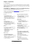
Chapter 1: Introduction 1.1 – Congratulations! You are now the owner of one of the most advanced dual Intel Xeon processor solutions available: the Thunder i7505 S2665. Based on Intel's E7505 chipset, the Thunder i7505 S2665 is Hyper-Threading ready - utilizing onboard resources so that many data threads can be handled with ease by two processors. With a 8x/4x AGP slot, six USB 2.0 and 1.
Integrated PCI IDE Form Factor § Provides two PCI bus master channels for up to four Enhanced IDE devices § Supports for UDMA 33/66/100 IDE drives and ATAPI compliant devices § Supports up to four Enhanced IDE devices § § § § § § § § § § Integrated I/O § Six USB 2.0 and 1.
Chapter 2: Board Installation Installation You are now ready to install your motherboard. The mounting hole pattern of the Thunder i7505 S2665 matches the EEB V3.0 specification. Before continuing with installation, confirm that your chassis supports a standard EEB V3.0 motherboard. How to install our products right….the first time! The first thing you should do is read this user’s manual. It contains important information that will make configuration and setup much easier.
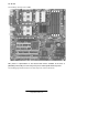
2.0 – Board The following is an image of the S2665. This picture is representative of the latest board revision available at the time of publishing. The board you receive may or may not look exactly like the above picture. The following page includes details on the vital components of this motherboard. 7 http://www.TYAN.
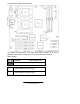
2.1 – Board Parts, Jumpers and Connectors This diagram is representative of the latest board revision available at the time of publishing. The board you receive may not look exactly like the above diagram. Jumper Legend Jumper OFF without jumper cover Jumper ON with jumper cover To indicate where the location of pin-1 To indicate where the location of pin-1 8 http://www.TYAN.
2.
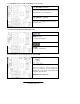
2.3 – AUX Audio Connect or (J8) and CD Audio Connector (J16) J 8 (AUX Audio connector) Connects to internal audio sources such as TV tuner, MPEG, or other similar cards J16 (CD Audio connector) Connects to a CD-ROM drive via an optional CD audio cable 2.4 – Ena ble/Disable Onboard LAN Jumper (J10) OPEN (Default) To enable onboard LAN CLOSE To disable onboard LAN 2.
2.6 – PS/2 ACPI Jumper (J12) pin-3 CLOSE Pins 1 and 2 (Default) To disable PS/2 devices’ ACPI wake up function pin-3 CLOSE Pins 2 and 3 To enable PS/2 devices’ ACPI wake up function 2.
2.9 – Disable Slot-B and Slot-C PCI-X Capability Jumper (J31) OPEN (Default) To enable PCI-X capability on Slot-B and Slot-C CLOSE To disable PCI-X capability on Slot-B and Slot-C Onboard SCSI chip PCI-X capability will be disabled due to sharing of the same bus 2.
2.12 – IEEE 1394 Connector (J66) Connects to a 1394 device via an optional 1394 cable 2.13 – LCD Connector (J69) Connects to a LCD display via an optional cable 2.14 – Front Panel Audio Connector (J71) Signal Description Pin # Pin # Signal Description Micro input 1 2 Analog GND Micro bias 3 4 Analog VCC Right line output 5 6 Right line return NC 7 8 Key Left line output 9 10 Left line return 2.15 – Chassis Intrusion Connector (J72) 13 http://www.TYAN.
Pin-1 Intrusion cable detection (low asserted) Pin-2 Intrusion detection (low asserted) Pin-3 GND 2.16 – Front Panel USB Header (J73) Signal Description Pin # Pin # Signal Description VCC 1 2 VCC Channel E Data negative 3 4 Channel F Data negative Channel E Data positive 5 6 Channel F Data positive GND 7 8 GND Key 9 10 Not connected 14 http://www.TYAN.
2.17 – Front Panel Connector (J74) Signal Description Sleep LED “ — “ Sleep LED “ + “ Key Power LED “ + “ Power LED “ + “ GND Message LED “+ “ Message LED “— “ Key HD LED “+ “ HD LED “— “ GND Power Button Sleep Button Reset Button Pin # 1 3 5 7 9 11 13 15 17 19 21 23 25 27 29 Pin # 2 4 6 8 10 12 14 16 18 20 22 24 26 28 30 Signal Description Speaker “— “ Key GND Speaker “+ “ Key Key Key Not connected SCSI LED Input SCSI LED Input Not connected Key GND GND GND 2.
2.20 – Mounting the Motherboard Before installing your motherboard, make sure your chassis has the necessary motherboard support studs installed. These studs are usually manufacturer pre-installed, metal and are gold in color. If you are unsure of stud placement, lay the motherboard inside the chassis and align the studs. NOTE YOU MUST make sure that there are no studs where there are no screw holes. 2.
Make sure that the memory you have is compatible with the motherboard as well as the processor. For example, DDR200 and DDR266 memory modules can be used for FSB=400MHz Intel Xeon processor but only DDR266 memory modules can be used for FSB=533MHz Intel Xeon processor.
2.22 – Installing the Processor(s) and Heatsink(s) Your Thunder i7505 S2665 supports the latest processor technologies from Intel. Check the following page on TYAN’s website http://www.tyan.com for latest processor support: The following diagrams will detail how to install your processor(s): Only identical CPUs can be used. REMINDER When installing only 1 processor, ensure to install it i n CPU socket 1 .
The following diagram will illustrate how to install the most common heatsinks: a. Align the heatsink mounting bracket to the holes around the processor socket b. Insert Black securing peg into bracket holes c. Insert White locking peg into Black securing peg d. Repeat process to mount all other brackets e. Seat heatsink between brackets on the processor f. Attach heatsink clips 19 http://www.TYAN.
Finishing Installing the Heatsink After you finish installing the heatsink onto the processor and socket, attach the end wire of the fan (which should already be attached to the heatsi nk) to the motherboard. The following diagram illustrates how to connect fans onto the motherboard. After you have finished installing all the fans you can connect your drives (hard drives, CD -ROM drives, etc.) to your motherboard. 2.
2.24 – Connecting External Devices The following diagrams will detail the rear port stack for this S2665 motherboard: a. Audio Port Line In Jack Connects to external devices for playback or recording Line Out Jack Connects to headphone or speakers (Amplifier integrated) Microphone In Jack Connects to an external microphone b. USB 2.0/1.1 USB 2.0 /1.1 Four rear USB 2.0/1.1 connectors Two front USB 2.0/1.1 headers (J73) c.
2.25– Installing the Power Supply There are three power connectors on your Thunder i7505 S2665. By default, the Thunder i7505 S2665 requires that you have an EPS12V power supply that has a 24 -pin and an 8-pin power connector. The extra 6-pin AUX power connector is recommended if you plan on using an AGP Pro video card. Please be aware that ATX 2.x, ATX12V and dual ATXGES (24+8-pin) power supplies are not compatible with the board.
2.26 – Attaching IDE and Floppy Drive Cables Attaching IDE drive cabling is simple. These cables are “keyed” to only allow them to be connected in the correct manner. Tyan motherboards have two on-board IDE channels, each supporting two drives. The black connector designates the Primary channel, while the white connector designates the Secondary channel.
2.27 – Finishing Up Congratulations on making it this far! You’re finished setting up the hardware aspect of your computer. Before closing up your chassis, make sure that all cables and wires are connected properly, especially IDE cables and jumpers. You may have difficulty powering on your system if the motherboard jumpers are not set correctly. In the rare circumstance that you have experienced difficulty, you can find help by asking your vendor for assistance.
Chapter 3: BIOS 3.0 – BIOS Setup Utility With the BIOS setup utility, you can modify BIOS settings and control the special features of your computer. The setup utility uses a number of menus for making changes and turning the special features on or off. All menus are based on a typical system. The actual menus displayed on your screen may be different and depend on the hardware and features installed in your computer. NOTE To start the BIOS setup utility: a. Turn on or reboot your system b.
3.1 – BIOS Menu Bar The menu bar at the top of the windows lists these selections: Main Advanced Security Power Boot Exit NOTE To configure basic sys tem setups To configure the chipset features To configure user and supervisor passwords To configure power management features To configure system boot order To exit setup utility Options written in bold type represent the BIOS setup default 3.
3.3 – BIOS Main Menu Main BIOS Setup Utility Security Power Advanced BIOS Version 1.00.xx 4Enable ACPI [Yes] 4Installed OS 4Reset Configur ation Data [Win2000/XP] [Yes] System Time System Date [12:59:59] [11/30/2002] Boot Exit Item Specific Help , , or selects field System Information F1 Help ESC Exit ⋅ Select Item √Select Menu -/+ Change Values F9 Setup Defaults Enter Select 4Sub- Menu F10 Save and Exit 3.3.
3.
3.4.4 – IDE Devices Sub -Menu Feature Primary/Secondary Master Primary/Secondary Slave Local Bus IDE Option Auto User ATAPI Removable CD-ROM None Auto User ATAPI Removable CD-ROM None Both Primary Secondary Disable Description Auto - To determine the IDE drive type by system BIOS User - To set IDE drive type by user ATAPI Removable - Read-and-write a media (e.g.
3.4.6 – Integrated SCSI / Network / USB / Audio /1394 Controller Sub -Menu Feature Integrated PCI Device Option Enabled Disabled Option ROM Scan Enabled Disabled Latency Timer Default 0020h 0040h 0060h 0080h 00A0h 00C0h 00E0h Description This setting determines whether the integrated PCI device is activated. This setting determines whether the option ROM of the integrated PCI device is loaded during system BIOS POST.
3.5 – BIOS Security Menu Main BIOS Setup Utility Security Power Advanced 4Set User Password 4Clear All Passwords 4Clear Supervisor Password 4Clear User Password F1 Help ESC Exit ⋅ Select Item √Select Menu Boot Exit Item Specific Help , , or selects field -/+ Change Values F9 Setup Defaults Enter Select 4Sub- Menu F10 Save and Exi t 3.
3.7 – BIOS Boot Menu Main BIOS Setup Utility Security Power Advanced 4Quick Boot Mode 4Display Option ROM Message 4Default Primary Video Adapter 4Boot Device Priority F1 Help ESC Exit ⋅ Select Item √Select Menu Boot Exit Item Specific Help , , or selects field -/+ Change Values F9 Setup Defaults Enter Select 4Sub- Menu F10 Save and Exit 3.7.
3.8 – BIOS Exit Menu Main Advanced BIOS Setup Utility Security Power 4Exit Saving Changes 4Exit Discarding Changes 4Load Setup Defaults 4Discard Changes 4Save Changes F1 Help ESC Exit ⋅ Select Item √Select Menu Boot Exit Item Specific Help , , or selects field -/+ Change Values F9 Setup Defaults Enter Select 4Sub- Menu F10 Save and Exit 3.8.1 – Exit Saving Changes Use this option to exit setup utility and re-boot. All new selections you have made are stored into CMOS.
Chapter 4: Diagnostics Note: if you experience problems with setting up your system, always check the following things in the following order: CPU, Memory, Video By checking these items, you will most likely find out what the problem migh t have been when setting up your system. For more information on troubleshooting, check the Tyan website at: http://www.tyan.com . 4.1 Beep Codes Fatal errors which halt the boot process are communicated through a seri es of audible beeps.
Appendix I: Glossary ACPI (Advanced Configuration and Power Interface): a power management specification that allows the operating system to control the amount of power distributed to the computer’s devices. Devices not in use can be turned off, reducing unnecessary power expenditure. AGP (Accelerated Graphics Port): a PCI-based interface which was designed specifically for demands of 3D graphics applications. The 32 -bit AGP channel directly links the graphics controller to the main memory.
Closed and open jumpers: jumpers and jumper pins are active when they are “on” or “closed”, and inactive when they are “off” or “open”. CMOS (Complementary Metal-Oxide Semiconductors): chips that hold the basic startup information for the BIOS. COM port: another name for the serial port, which is called as such because it transmits the eight bits of a byte of data along one wire, and receives data on another single wire (that is, the data is transmitted in serial form, one bit after another).
IDE (Integrated Device/Drive Electronics): a simple, self-contained HDD interface. It can handle drives up to 8.4 GB in size. Almost all IDEs sold now are in fact Enhanced IDEs (EIDEs), with maximum capacity determined by the hardware controller. IDE INT (IDE Interrupt): a hardware interrupt signal that goes to the IDE. I/O (Input/Output): the conne ction between your computer and another piece of hardware (mouse, keyboard, etc.
RAM (Random Access Memory): technically refers to a type of memory where any byte can be accessed without touching the adjacent data and is often referred to the system’s main memory. This memory is available to any program running on the computer. ROM (Read-Only Memory): a storage chip which contains the BIOS; the basic instructions required to boot the computer and start up the opera ting system.
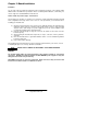
Technical Support If a problem arises with your system, you should turn to your dealer for help fi rst. Your system has most likely been configured by them, and they should have the best idea of what hardware and software your system contains. Furthermore, if you purchased your system from a dealer near you, you can bring your system to them to have it serviced instead of attempting to do so yourself (which can have expensive consequences). Help Resources: 1. See the beep codes section of this manual. 2.
Notice for the USA Compliance Information Statement (Declaration of Conformity Procedure) DoC FCC Part 15: This device complies with part 15 of the FCC Rule s Operation is subject to the following conditions: 1) 2) This device may not cause harmful interference, and This device must accept any interference received including interference that may cause undesired operation.