Transport GS12 / / / B5103G12S2 Revision 1.00 Copyright © TYAN Computer Corporation, 2004. All rights reserved. No part of this manual may be reproduced or translated without prior written consent from TYAN Computer Corp. All registered and unregistered trademarks and company names contained in this manual are property of their respective owners including, but not limited to the following: TYAN, Transport GS12 B5103G12S2 are trademarks of TYAN Computer Corporation.
1 1 2 3 Table of Contents Before You Begin ............................................................................ 5 Safety Precautions ........................................................................... 4 Introduction .......................................................................................................... 7 1.1 Unpacking........................................................................................ 7 1.2 Product Description .......................................
4 5 6 LCD Driver .................................................................................... 30 Intel Application Accelerator......................................................... 31 ASF Alert Simulation and WatchDog Drivers............................... 31 ASF (Alert Standard Format) 2.0 SDK.......................................... 31 3.2 Installation Instructions for Linux (Red Hat/SuSE/Turbo Linux).. 33 Red Hat Linux 9.0 Installation Notes.............................................
7 8 9 6.3 About ASF 2.0 ............................................................................... 65 Set up Management Console ......................................................... 65 Check Agent and Management Console Link ............................... 66 Obtain Traps and Push Messages .................................................. 68 Remote Control.............................................................................. 69 Expanding the System.......................................
Before You Begin This manual provides hardware-related information of the system for administrators who use it to develop and host web sites. The administrators should be familiar with operating systems and web browsers. Depending on the model purchased, your system may come with pre-installed software. For software information, refer to the documentation accompanying the software. Safety Precautions l Use the type of power indicated on the marking label.
1 Introduction Congratulations on purchasing the system. This chapter introduces the features and functions of the product. 1.
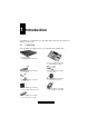
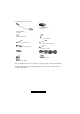
And the following accessories: P/N 343728700001 1× heatsink P/N 451715600031 1× rail kit 1× primary IDE cable 1× secondary IDE cable 1× primary serial ATA cable 1× secondary serial ATA cable 1× HDD power to pinheader cable 2× SATA power cable 4× rubber feet 2× power cord (USA and Germany) 1× TYAN driver CD 1× B5103 User’s Manual Inspect all the items. If any item is damaged or missing, notify your dealer immediately.
1.2 Specifications NOTE: Specifications are subject to change without notice. Processor • Single socket 478 • Intel Pentium 4 Northwood/Prescott processor • Supports 533/800 MHz FSB Chipset • Intel 875P MCH • MCH+ICH-5R • SMC LPC47M172 Super I/O chip Memory • Two 64-bits wide DDR data channels • Single/dual-channel mode support • Four 184-pin DDR DIMM slots • DDR 266/333/400 MHz support • Up to 4 GB of unbuffered DDR • Supports non-ECC/ECC-type memory modules Expansion Slot • One 32-bit/33MHz PCI v2.
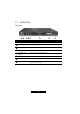
1.3 System View Front View Ref Component Description Œ • Ž • • Power Button Turns the power on and off (soft-off). Power Indicator Glows green when the power is on. LAN1 Indicator Indicates a network connection on LAN1 (external connection). LAN2 Indicator Indicates a network connection on LAN2 (internal connection). Hard Disk Drive Indicator Indicates activity on the hard disk drive. ‘ ’ “ USB Ports Each of the two ports connects a USB device.
Rear View Ref Component ΠVentilation Openings Maintain proper operating temperature. Do not cover or block the openings. Power Connector Connects the power cord. Power Switch Turns the main power of the system on and off. LAN1 Connector Connects the LAN cable for internal network connection. LAN2 Connector Connects the LAN cable for external network connection. Serial Port Connects a serial device. VGA Port Connects an external CRT monitor.
2 Hardware Installation This chapter, which is divided into two sections, provides instructions on the hardware installation of the system. System Assembly section illustrates how to assemble each component of the system. Rack Mounting section describes the procedures for mounting the system into the rack. You can use the system assembly flowchart and the chart next to determine the proper sequence for removing or installing components to the server.
System Assembly Flowchart The following flowchart shows the basic procedures of system assembly: START CONNECT HARD DISK DRIVE CABLE AND POWER CORD REMOVE CABINET COVER CHECK IF ALL PARTS ARE PROPERLY CONNECTED INSTALL CPU AND HEATSINK REPLACE CABINET COVER INSTALL SYSTEM MEMORY FINISH INSTALL HARD DISK DRIVE 14 http://www.TYAN.
2.1 System Assembly When installing a device, be sure to read the instructions accompanying the device together with the relevant section in this chapter. Safety Considerations l Static electricity can destroy electronic devices. Whenever you handle an option outside of its protective packaging, first discharge any static electricity from your body by touching a protective grounding device or unpainted metal on the rear panel of the system before unplugging the power cord.
3. Lift the socket arm up to the vertical position. Align the new CPU so its Pin 1 corner (beveled corner) is at the Pin 1 corner of the socket. 4. Insert the CPU pins into the socket. Press the arm downward to the horizontal position. You will feel some resistance while doing so. This is normal as the pressure starts to secure the CPU in place. 5. Place the heatsink assembly on top of the CPU and align the four points of the heatsink socket. Secure with four screws following a diagonal sequence.
6. Replace the cabinet cover. Installing System Memory Your system has four 184-pin DIMM (Dual In-line Memory Module) sockets to support a maximum of 4 GB. You must follow these requirements for the DIMM to be used with the system: l Unbuffered DDR-SDRAM (Double Data Rate Synchronous DRAM) with ECC l PC2100/PC2700/PC3200-compliant l 2.5 V Follow this procedure to install a DIMM: 1. Open the cabinet cover (see previous section). 2. Locate the DIMM sockets. 17 http://www.TYAN.
3. To install the DIMM, make sure the retaining clips are in the unlocked position, then align the DIMM’s notched end with the socket’s corresponding end and firmly insert the DIMM into the socket. Finally push the retaining clips inwards to lock the DIMM in place. 4. Replace the cabinet cover. Installing a Hard Disk Drive NOTE: Make sure that the jumper setting of the hard disk drive is set to “Master.”(See the hard disk drive’s documentation for information.) 1.
4. Fit the bracket with a hard disk drive back into place and secure with one screw. If using an Ultra ATA/100 hard disk drive, connect the corresponding end of the included HDD power to pin header cable to the motherboard (Œ) and the other end to the hard disk drive (•) . Connect the included primary IDE data cable to the primary IDE connector on the motherboard (Œ) and the other end to the hard disk drive (•).
5. Replace the cabinet cover. 6. You can create or rebuild RAID for the hard disk drive (see chapter 6 for information). 2.2 Adding a CD Drive You will need to use a CD drive when installing an operating system and its corresponding drivers (see chapter 3). WARNING: You are advised not to make frequent connection and disconnection on the IDE connector as this might cause damage to the data cable and connector pins. CAUTION: Follow the instructions in this section carefully.
Without a Secondary Ultra ATA/100 Hard Disk Drive Installed 1. Remove the cabinet cover (see the previous section in this chapter). 2. Connect one end of the data cable to the secondary IDE connector and the other end to the rear of the CD drive (Œ). 3. Connect the power cord to the rear of the CD drive (•). NOTE: You cannot replace the cabinet cover with a CD drive installed. Remove the CD drive after using it to be able to replace the cabinet cover. 2.
You should find these standard items: l 2 mounting ears l 2 rack slides (inner and outer slides) l 4 post slide mount adapters l hex screws (+) and hex nuts (for outer slides) l hex screws (for slide mount adapter – dark colored) Cabinet Slides and Ears 1. Attach the mounting ears to the side near the front of the cabinet. Then secure each with two screws. 2. Detach the inner slide from the outer slide by pressing on the release latch Œ and pulling apart the inner slide from the outer slide •.
4. Attach a post slide mount adapter to the front end of the outer slide by securing 2 sets of hex screws and hex nuts together. 5. Attach a post slide mount adapter to the rear end by moving the inner rails to expose the screw holes. Do the same for the other outer slide. 6.
Locking Tab To prevent the system chassis from sliding on its rails, secure the system cabinet to the rack with a screw on each of the mounting ears Ž (optional – refer to the figure above). 2.4 Setting Up the System To use the system, you need: l A 10Base-T, 10/100Base-TX, 100Base-TX or 1000Base-T TCP/IP-based LAN l A computer connected to the network that uses a Web browser (Netscape Navigator or Microsoft Internet Explorer, version 4.
Making the Connection 1. Connect one end of a Category 5 Ethernet cable to the LAN1 connector on the system and the other end to the network socket that connects to the external network. 2. Connect one end of a Category 5 Ethernet cable to the LAN2 connector on the system and the other end to the network socket that connects to the clients. 3. Connect one end of the power cord to the system and the other end to an electrical outlet. 4.
7. Press the power button to turn on the system. The hard disk drive spins up, the fan turns on, and the LCD screen lights up. A number of status messages are displayed on the screen during the boot process. CAUTION: It is important to follow the proper power-down procedure for turning off the system. 26 http://www.TYAN.
3 Software Installation You need to install an operating system and its corresponding software drivers using the CD supplied with your system. The drivers are required for taking full advantage of its unique features. As of the publication of this User’s Manual, the drivers presently available on the CD and the OS supported are shown on the next table: Driver LCD driver Watchdog driver ASF Alert Simulation OS Windows 2000 Windows 2000 SBS Windows 2003 Windows 2003 SBS Windows XP RedHat Linux 9.
Driver ASF Alert Simulation ASF (Alert Standard Format) 2.0 SDK RAID function OS SuSE Linux 8.1 Turbo Linux 8 FreeBSD 4.7 Windows 2000 Windows 2000 SBS Windows 2003 Windows 2003 SBS Windows XP RedHat Linux 9.0 SuSE Linux 8.1 Turbo Linux 8 FreeBSD 4.7 Windows 2000 Available on CD Not Available Not Available Not Available ü ü ü ü ü Not Available Not Available Not Available Not Available ü Windows 2000 SBS ü Windows 2003 Not Available Windows 2003 SBS Not Available Windows XP ü RedHat Linux 9.
3.1 Installation Instructions for Windows Windows Installation Notes Proceed with the normal Windows operating system installation but if you are installing Windows on to a Serial ATA hard disk drive with RAID function, do the following first: 1. Create a RAID driver floppy disk by inserting a blank floppy disk and the driver CD into the floppy drive and CD drive respectively, on another Windows system. 2. Run the iaar2_floppy.exe program in the \Intel_8xx\i8xx_UATA\ IAAR\3.5.3\ directory.
2. Run the wxp-ragex1-5-10-2600-6009.exe program in the \ATI_RageXL\ XP\ directory. 3. Follow the onscreen instructions to complete the installation. 4. When finished installing, choose the “Yes” option to reboot and click “Finish” to restart your system. The driver should now be loaded. LAN Driver 1. Insert the driver CD into the CD drive. 2. Run the proXXX.exe program in the \LAN\Intel\Pro100_1K\V8.2\ directory. 3. Follow the onscreen instructions to complete the installation. 4.
When installation asks for the CD, just click "OK" and browse the path again to \LCD\GS12\Windows\driver\LCDDriver.sys, then click Open->OK to finish the LCD driver installation. 3. Start the LCD service in Windows Operating System For Windows 2000 Small Business Server system, run \LCD\GS12\Windows\ W2KSBS\install.bat, or else run \LCD\GS12\Windows\service\ install.bat 4. Follow the onscreen instructions to complete the installation. 5.
Click on “Have Disk” to browse and point the folder to the driver location at \ASF\Windows\driver\ASF_Simulation\hwdriverchecked.inf and click Open->OK. When installation asks for the CD, just click on "OK" and browse the path again to \ASF\Windows\driver\ASF_Simulation\ then click on Open->OK to finish the ASF driver installation. 3.
3.2 Installation Instructions for Linux (RedHat /SuSE/Turbo Linux) NOTE: Do not allow USB devices to be hot plugged during installation of the Linux operating system. RedHat Linux 9.0 Installation Notes Proceed with the normal installation of RedHat Linux 9.0 operating system. If you are using the SMP kernel, in order to allow a complete system shutdown, then perform the following: 1. Modify the /boot/grub/grub.conf by adding the boot parameter apm=power_off. Then save and exit. 2.
4. Use the command uname –r to check which kernel the system is using. If the kernel is 2.4.18-5smp, modify the file /boot/kernel.h as follows: #define __BOOT_KERNEL_SMP 1 If you are using the SMP kernel, in order to allow a complete system shutdown, then perform the following: 1. Modify the /boot/grub/ grub.conf by adding the boot parameter apm=power_off. Then save and exit. 2. Run the command grub-install /dev/hda, then reboot the system. Next, proceed to the following driver installations.
LCD Driver 1. Insert the driver CD into the CD drive. 2. Copy MiSM_LLCDxx_for_yyy.tar.gz of the /LCD/GS12/Linux/ directory to the directory of your choice (where xx refers to the version and yyy refers to the operating system). 3. Untar/unzip archive: tar zxf MiSM_LLCDxx_for_yyy.tar.gz. 4. Change to the driver SRC directory: cd MiSM_LLCDxx_for_yyy/. 5. Install the LCD driver: ./LCDinstall. 6. Confirm that the NICs can be enabled when the system starts. 7. Reboot the system.
3. Untar/unzip archive: tar xfvz asfm-x.x.tar.gz. 4. Change to the driver directory: cd asfm-x.x. 5. Install the WatchDog driver: make make install. 3.3 Installation Instructions for FreeBSD 4.7 NOTE: Do not allow USB devices to be hot plugged during installation of the Linux operating system. FreeBSD 4.7 Installation Notes NOTE: As of the writing of this User’s Manual, your system only supports the FreeBSD 4.7 operating system. This is because FreeBSD 5.1/5.
Then save and exit. /usr/sbin/config MYKERNEL cd ../../compile/MYKERNEL make depend make make install vi /etc/rc Add the line apm -e 1 before the last line exit 0. Then save and exit. Reboot the system. You can now use the new kernel. Run the command halt -p to shutdown the system completely. LAN Driver NOTE: To compile the driver into the kernel, go directly to step 4. 1. Insert the driver CD into the CD drive. 2. Copy the base driver tar file em-1.7.15.tar.
dev/em/if_em_hw.c optional em Remove the following lines from the /usr/src/sys/conf/files.i386 file if they exist: dev/em/if_em_fxhw.c optional em dev/em/if_em_phy.c optional em Edit the kernel configuration file (i.e., GENERIC or MYKERNEL) in /usr/src/ sys/i386/conf and ensure the following line is present: device em Compile and install the kernel, the system must be rebooted for the kernel updates to take effect.
USB Floppy Drive Usage If your USB floppy drive cannot be used normally, please add one line on /etc/sysctl.conf: kern.cam.da.no_6_byte=1. Then reboot your system. 3.4 Installation Instructions for Solaris 9 Solaris 9 Installation Notes Proceed with the normal Solaris 9 operating system installation but since Serial ATA controllers are not compatible with IDE (Parallel ATA) controllers, they need a different driver that is not included in the Solaris 9 installation kernel.
4 Using the LCD Console This chapter tells you how to use the LCD console to make various system configurations. 4.1 Configuring the System After you have made the network and power connections, you can configure the network settings using the LCD console. Before You Begin NOTE: To take advantage of the LCD console feature, make sure that the LCD driver is correctly installed (see chapter 3).
The Down arrow button decreases the digit located at the cursor position. The S (Select) button accepts the data entered or selects the option displayed. The C (Cancel) button cancels the data entered or the option displayed. 4.2 Setting the Configuration For Windows Press the corresponding button according to the number of times specified on the following table and you will see the corresponding prompt.
KEY PRESS Down arrow four (4) times Down arrow five (5) times Down arrow six (6) times PROMPT FUNCTION HW Monitor Display Upon each succeeding press of the Right arrow, the value of the following appear, depending on your settings under HW Monitor List Configure (down arrow sixth time – see below): Do you want to display? (default is Yes) CPU Temp Local Temperature System Temperature Fan1 Speed Fan2 Speed Fan3 Speed Vcc 2.6V VCCP Vcc 3.
KEY PRESS Down arrow seven (7) times Down arrow eight (8) times PROMPT FUNCTION Performance List Configure Upon each succeeding press of the Right arrow, the following appears.
4.3 Setting the Configuration For Linux Press the corresponding button according to the number of times specified on the following tables, and you will see the corresponding prompt. NOTE: If you press the C (Cancel) button at any time to cancel the configuration, you must go through the entry process for a particular setting again.
KEY PRESS Down arrow five (5) times Down arrow six (6) times PROMPT HW Monitor Display Upon each succeeding press of the Right arrow, the value of the following appear, depending on your settings under HW Monitor List Configure (down arrow eighth time – see below): HWM Display (default is Yes) VCC 2.6V VCCP VCC 3.
KEY PRESS Down arrow nine (9) times Down arrow ten (10) times PROMPT FUNCTION Performance List Configure Upon each succeeding press of the Right arrow, the following appears.
4.4 Setting the Configuration For FreeBSD Press the corresponding button according to the number of times specified on the following tables, and you will see the corresponding prompt. NOTE: If you press the C (Cancel) button at any time to cancel the configuration, you must go through the entry process for a particular setting again.
KEY PRESS Down arrow five (5) times Down arrow six (6) times PROMPT HW Monitor Display Upon each succeeding press of the Right arrow, the value of the following appear, depending on your settings under HW Monitor List Configure (down arrow eighth time – see below): HWM Display (default is Yes) Temp1 Temp2 Temp3 Rot1 Rot2 Rot3 VC0 VC1 V3.3 V5.
KEY PRESS Down arrow nine (9) times Down arrow ten (10) times PROMPT FUNCTION Performance List Configure Upon each succeeding press of the Right arrow, the following appears.
5 BIOS Setup 5.1 BIOS Setup Program BIOS Setup (SCU or Setup Configuration Utility) is a program for configuring the BIOS (Basic Input/Output System) settings of the system. You need to run the BIOS Setup program when: l You see an error message on the screen requesting you to run Setup. l You want to restore the factory default settings. l You want to modify some specific settings according to the hardware. l You want to modify some specific settings to optimize system performance.
Key Function Enter Pops up an option window for the highlighted field. Esc 1) Returns to the main menu from a sub-menu. 2) Exits Setup. F9 Restores the Setup defaults. F10 Saves changes and exits Setup. Main Menu The Main menu contains the basic configuration settings of your system. System Time sets the system time (Hour, Minute, Second). System Date sets the system date (Day, Month, Year).
Legacy USB Support enables or disables support for Legacy Universal Serial Bus in non-USB-aware operating systems like DOS. Spread Spectrum enables or disables the Spread Spectrum function to reduce the EMI (Electro-Magnetic Interference) effect. Advanced Chipset Control Graphics Aperture sets the memory size of AGP VGA device. USB 2.0 Controller enables or disables USB 2.0 controller. ECC Config allows you to enable or disable support for ECC-type of memory.
CAUTION: Set this item to disabled before installing an operating system, running Fdisk or Format program, or when re-installing software. Otherwise, the intended action will fail. Virus Check Reminder displays the virus check reminder message during system boot up. System Backup Reminder displays the system back up reminder message during system boot up. Password on Boot determines if the system will request a password when starting up.
Fan Mode Configuration allows you to select the system fan’s working mode. When set at Disabled (default), all system fans will run at full speed. When set at Smart mode, the fan will automatically adjust its speed according to the set temperature. The advantages of choosing Smart mode are reduced noise, reduced wear by increasing the lifetime and reliability of fans, as well as reduced power consumption. Overall, it helps extend the system’s life by minimizing the rate at which the system collects dust.
5.2 Resetting BIOS Setup When you want to reset the BIOS configuration, you need to change the jumper setting. See the next figure for jumper location and the table that follow for jumper definition. CAUTION: Jumpers not described in this section are reserved for factory use only. Do not change the default settings. Jumper J2 Definition CMOS setting Setting Description 1-2 Normal (default) 2-3 Clear CMOS To clear the RTC and CMOS RAM, set J2 to 2-3 for one second and set it back to 1-2 again.
6 Using RAID and ASF 2.0 6.1 About RAID NOTE: You need to install two Serial ATA hard disk drive and running Windows XP or Windows 2000 in order for your system to support RAID (Redundant Array of Inexpensive Disk). The purpose of RAID is to combine multiple small, inexpensive disk drives into an array of disk drives that appears to the system as a single logical storage device and yields performance exceeding that of a Single Large Expensive Drive (SLED).
6.2 Creating an Array 1. Make sure that you have installed the Intel Application Accelerator program (refer to chapter 3). Also, you need to install two Serial ATA disk drives to the motherboard (refer to chapter 7). 2. Boot up with Windows 2000 or Windows XP. 3. Run the Intel Application Accelerator program. 4. Create your desired array. See the following subsections for details. Creating an Array for Performance (RAID 0) 1. Select RAID, then Create Volume Manually. 58 http://www.TYAN.
2. Select RAID 0 under the item Select RAID Level, then click on Next. 3. Click on Yes (Y) to continue. 59 http://www.TYAN.
4. Click on Create to create the new RAID volume. 5. Click on OK to finish. 60 http://www.TYAN.
Creating a Security Array (RAID 1) 1. With the Intel Application Accelerator program running, select RAID, then click on Create Volume Manually. 2. Select RAID 1 under the item Select RAID Level, then click on Next. 61 http://www.TYAN.
3. Click on Yes (Y) to continue. 4. Click on Yes (Y) to continue. 62 http://www.TYAN.
5. Click on Create to create the new RAID volume. 6. Click on OK to finish. Creating RAID With an Existing Data Drive Use this method if you have a Serial ATA disk drive that already contains data or is the boot device in your system. You will need another Serial ATA disk drive of identical or larger storage capacity. 63 http://www.TYAN.
1. With the Intel Application Accelerator program running, select RAID, then click on Create Volume from Existing Disk. 2. Select a source disk, then click on Next. 3. Then, follow the steps outlined in the previous sections Creating an Array for Performance (RAID 0) and Creating a Security Array (RAID 1). 64 http://www.TYAN.
6.3 About ASF 2.0 NOTE: You need to be running Windows XP, Windows 2000 or Windows 2003 in order for your system to support ASF 2.0 (Alert Standard Format). ASF 2.0 enables remote systems to activate security features as well as control your system (e.g., power on, power off, system reset, power cycle, etc.) whether with or without an operating system running. Set Up Management Console Using another system, set up the ASF 2.
Check Agent and Management Console Link 1. To check the link between the Agent and the Management Console, ping each other’s IP address (ipconfig and ping). 2. Run the alertAPP.exe file located on the Agent’s system and log in directly without having to type anything, then check that the following configurations are set correctly: Check the option Enable ASF. Select the correct adapter. Enter the correct Management Console’s address. The Alerting Enabled Status indicator should light. 66 http://www.
3. Run the ASFMgmtConsole.exe file on the Management Console, then check if the data from the Agent is correct. 67 http://www.TYAN.
Obtain Traps and Push Messages 1. Run AlertApp to set Heartbeat. 2. Run ASFMgmtConsole to obtain Alert from the Agent. 68 http://www.TYAN.
Remote Control 1. To generate Key from Management Console, run ASFMgmtConsole to generate the Administrator Key. 2. Save the Key from Management Console into a floppy disk. 3. Run AlertApp to load the Security Key to the Agent. 69 http://www.TYAN.
4. Run AlertApp to select the Remote Control functions supported by the system. 5. Run ASFMgmtConsole to select and execute Remote Control operations (send secured RMCP). 70 http://www.TYAN.
7 Expanding the System You can expand the capabilities of the system by adding or upgrading internal devices. When installing a device, be sure to read the instructions accompanying the device together with the relevant section in this chapter. 7.1 Opening the Cover CAUTION: l Static electricity can destroy electronic devices.
7.2 Installing an Expansion Card Your system supports one PCI slot located on a riser card. You can install a PCI expansion card for additional or enhanced functions. Follow this procedure to install an expansion card: 1. Before you purchase a PCI expansion card to add to the system, make sure that the card is less than 7 inches (177.8 mm) long. Otherwise, it will not fit into place. 2. Open the cabinet cover (see the previous section in this chapter). 3.
5. Replace the cabinet cover. NOTE: According to the standard X86 structure, there is only 128 k (C0000h-DFFFFh) shadow RAM for system option ROM. For this system, the RAID card option ROM engrosses 64 k, the onboard ATI VGA card engrosses 32 k, the onboard LAN engrosses more than 10 k, so the remaining space for option ROM is very limited. You may encounter the possibility that some PCI cards (e.g., SCSI PCI card) cannot be initialized and used when the PCI card needs more shadow RAM for its option ROM.
Secondary IDE Connector 3. Secure the hard disk drive to the bracket with four bottom screws. 4. Fit the bracket with the hard disk drive back into place and secure with one screw. 5. If using an Ultra ATA/100 hard disk drive, connect one end of the included secondary IDE data cable to the secondary IDE connector (see figure above) and the other end to the rear of the hard disk drive. Then connect the power cord.
6. You can create RAID for the hard disk drives (see Chapter 6 for information). 75 http://www.TYAN.
8 System Parts Replacement In case the need arises, you can replace various system components. When removing and installing a device, be sure to read the instructions accompanying the device together with the relevant section in this chapter. 8.1 Opening the Cover CAUTION: l Static electricity can destroy electronic devices.
8.2 Removing the Front Bezel Care must be taken to ensure that the latches on the front bezel used to attach it to the system chassis does not break. Follow this procedure to detach it from the system chassis: 1. Open the cabinet cover (see the previous section in this chapter). 2. Remove the primary hard disk drive (see chapter 2 on Installing a Hard Disk Drive). 3.
Reverse the above sequence when installing the new button board. 8.4 Replacing the Fan There are two fans located at the front of the system. To replace either one, follow these procedures. 1. Remove the cabinet cover (see the previous section in this chapter). 2. Remove the front bezel (see the previous section in this chapter). 3. Remove the heatsink screws following a diagonal sequence to detach the heatsink. Remove either side’s fan cable connector.
8.5 Replacing the USB Board The USB board contains the circuitry for the two USB ports located on the system’s front panel. To replace it, follow these procedures. 1. Remove the cabinet cover (see the previous section in this chapter). 2. Remove the front bezel (see the previous section in this chapter). 3. Remove the two screws securing the USB board to the system chassis and detach the USB board to pin-header cable from the connector on the motherboard.
Reverse the above sequence when installing the new LCD module. 8.7 Replacing the Power Supply To replace the system’s power supply, follow these procedures. 1. Remove the cabinet cover (see the previous section in this chapter). 2. Remove the secondary hard disk drive (see chapter 7 on Adding a Secondary Hard Disk Drive). 3. Detach the 4-pin 12 V plug from the ATX 12 V connector on the motherboard as well as the 20-pin connector from the ATX connector on the motherboard. Then, remove the two screws. 4.
Reverse the above sequence when installing the new power supply. 8.8 Replacing the Blower To replace the system’s blower, follow these procedures. 1. Remove the cabinet cover (see the previous section in this chapter). 2. Remove the two screws securing the blower to the system chassis and detach the blower to pin-header cable from the connector on the motherboard. Reverse the above sequence when installing the new blower. 8.9 Replacing the Motherboard To replace the motherboard, follow these procedures.
5. Remove the heatsink screws following a diagonal sequence to detach the heatsink and remove the CPU from its socket. 6. Detach the DIMM from the socket on the motherboard. 7. Detach the riser card from the PCI slot on the motherboard. 8. Remove the four hex screws on the serial and VGA ports on the rear panel. 9. Remove the eight screws securing the motherboard to the system chassis. Reverse the above sequence when installing the new motherboard. 83 http://www.TYAN.
9 Appendix Caution Texts Concerning Lithium Batteries DANISH ADVARSEL! Lithiumbatteri - Eksplosionsfare ved fejlagtig håndtering. Udskiftning må kun ske med batteri af samme fabrikat og type. Levér det brugte batteri tilbage til leverandøren. NORWEGIAN ADVARSEL: Eksplosjonsfare ved feilaktig skifte av batteri. Benytt samme batteritype eller en tilsvarende type anbefalt av apparatfabrikanten. Brukte batterier kasseres i henhold til fabrikantens instruksjoner.
FRENCH ATTENTION: II y a danger d’explosion s’il y a remplacement incorrect de la batterie. Remplacer uniquement avec une batterie du même type ou d’un type équivalent recommandé par le constructeur. Mettre au rebut les batteries usagées conformément aux instructions du fabricant. Technical Support If a problem arises with your system, you should turn to your dealer for help first.
Notice for the USA Compliance Information Statement (Declaration of Conformity Procedure) DoC FCC Part 15: This device complies with part 15 of the FCC Rules Operation is subject to the following conditions: 1. This device may not cause harmful interference, and 2. This device must accept any interference received including interference that may cause undesired operation.