B4881V50S4H User Manual Document part number: D1652-100
Preface Copyright This publication, including all photographs, illustrations, and software, is protected under international copyright laws, with all rights reserved. Neither this manual, nor any material contained herein, may be reproduced without written consent of the manufacturer. Copyright 2005 Version 1.00 Disclaimer Information contained in this document is furnished by TYAN Computer Corporation and has been reviewed for accuracy and reliability prior to printing.
Federal Communications Commission Notice for the USA Compliance Information Statement (Declaration of Conformity Procedure) DoC FCC Part 15: This device complies with part 15 of the FCC Rules Operation is subject to the following conditions: 1) This device may not cause harmful interference, and 2) This device must accept any interference received including interference that may cause undesired operation.
About this manual This manual provides you with instructions on installing your B4881V50S4H, and consists of the following sections: Chapter 1 – Overview: Provides an introduction to the B4881 V50S4H barebones, shows a packing list, describes the external components, shows tables of key components, and provides a block diagram of the system. Chapter 2 – Setting up: Covers procedures on installing the CPUs, memory modules, optional PCI card, and hard drives.
Safety information Before installing and using the B4881V50S4H, take note of the following precautions: iv • • • Read all instructions carefully. • Only use the power source indicated on the marking label. If you are not sure about your power source, contact the power company. • The unit uses a three-wire grounded cable, which is supplied with a third pin to ground the unit and prevent electric shock. Do not defeat the purpose of this pin.
Table of Contents Chapter 1: Overview 1.1 About the B4881V50S4H................................................... 1 1.2 Features............................................................................. 2 1.3 Unpacking .......................................................................... 3 1.3.1 Box contents ................................................................ 3 1.3.2 Accessories ................................................................. 4 1.3.3 Opening the box ..................
3.5 Replacing the SATA backplane ....................................... 41 3.6 Replacing power supplies ................................................ 43 3.7 Replacing cooling fans..................................................... 43 Appendix BIOS ....................................................................................... Introduction .......................................................................... Hardware monitor submenu.................................................
Chapter 1: Overview 1.1 About the B4881V50S4H Congratulations on your purchase of the B4881V50S4H, rack mountable or standalone, barebone system. This product supports up to 8 AMD Opteron™ 800 series processors and 128 GB of registered DRAM, offering exceptional computing power and simultaneous support of 32-bit and 64-bit applications.
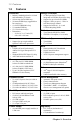
1.2 Features 1.2 Features Enclosure • Industry standard pedestal or 19-inch rack mountable, 5U chassis • (4) hot swap SATA HDD bays • (4) internal HDD bays (upgradable to hot swap bays) • (1) slim CD-ROM drive bay • (1) standard FDD bay • (3) 3.5-inch device bays • Dimensions: - 26.8 x 16.7 x 8.7-inch (5U) - 680 x 425 x 220 mm Processors • Support for up to eight AMD® Opteron™ 800 series processors.
1.3 Unpacking 1.3 Unpacking This section describes the B4881V50S4H package contents and accessories. 1.3.1 Box contents Component Description Industry standard 5U chassis with eight HDD bays and three further 5.
1.3 Unpacking Component Description Up to four 500W hot-swap power supplies Three system cooling fans (preinstalled) 120 x 120 x 38 mm Four or eight processor heatsink assemblies (pre-installed) 1.3.2 Accessories Rack mounting kit; mounting ears, and rail assembly Four feet for standalone use Cable set: • (4) SATA cables • (1) 40-pin IDE ribbon cable • (1) 34-pin FDD ribbon cable • (8) power cord 4 x US, 4 x EU Four internal hard disk drive mounting kits WWW.tyan.
1.3 Unpacking 1.3.3 Opening the box Open the box carefully and ensure that all components are present and undamaged. The product should arrive packaged as illustrated below. Accessory pack Power cables and disk mounting kit Server door Contact your distributor if anything is missing or appears damaged.
1.4 About the product 1.4 About the product This section contains hardware diagrams and a block diagram of the B4881V50S4H system. 1.4.1 System front view and front panel See the diagram below for details of the front panel indicators and switches. Hotswap HDD bays USB ports Internal HDD bays Slim CD-ROM drive Power id Reset 5.25-inch device bays Floppy disk drive LED control panel 1.4.
1.4 About the product 1.4.3 System internal view 1 10 2 3 4 5 6 7 8 9 1 Hard disk drive cradles 6 SATA ports 2 SATA backplane 7 Floppy disk drive socket 3 System cooling fans 8 PCI slots 4 Memory bank 9 CPU 5 IDE socket (CD-ROM drive) 10 Cradle for 5.
1.4 About the product 1.4.
1.4 About the product 1.4.
1.4 About the product 1.4.
Chapter 2: Setting up 2.1 Before you begin This chapter explains how to install motherboard components, including CPUs, memory modules, and PCI cards. There are also instructions in this section for installing SATA hard drives. Careful attention should be given to the precautions mentioned in this section when setting up your system. 2.1.1 Work area Make sure you have a stable, clean working environment. Dust and dirt can get into components and cause malfunctions.
2.1 Before you begin 2.1.3 Precautions Components and electronic circuit boards can be damaged by static electricity. Working on a system that is connected to a power supply can be extremely dangerous. Follow the guidelines below to avoid damage to the B4881V50S4H or injury to yourself. • • • • • • • Note: 12 Ground yourself properly before removing the top cover of the system. Unplug the power from the power supply and then touch a safely grounded object to release static charge (i.e.
2.2 Installing motherboard components 2.2 Installing motherboard components This section describes how to install CPUs, memory modules, and expansion cards. 2.2.1 Removing the chassis cover Follow these instructions to remove the chassis cover. This step is required before any other procedures in this chapter can be undertaken. 1. Press the two blue buttons on the release catches and lift the catches. The chassis lid slides back slightly. 2. Lift the lid free from the chassis.
2.2 Installing motherboard components 2.2.2 Installing CPUs and heatsinks This section describes how to install AMD Opteron processors and heatsinks on the B4881V50S4H motherboard and CPU expansion board. 1. Remove the chassis cover. See Removing the chassis cover on page 13. 2. Remove the optional processor board if it is present, see “Replacing the CPU expansion board” on page 37 3. Locate the four CPU sockets on the motherboard or CPU expansion board. CPU sockets 1-4 4.
2.2 Installing motherboard components 5. Place the CPU in the socket as shown, making sure that pin 1 is located correctly. 6. Push the CPU locking lever down to lock the CPU in place. Locking lever 7. Take a new heatsink and remove all packaging and covers from it. 8. Apply some thermal grease to the top of the CPU and place a heatsink on top of the CPU as shown. Note: All heatsink fans must face the rear of the chassis to ensure proper airflow.
2.2 Installing motherboard components 9. Screw the heatsink to the heatsink retainer as shown. Heatsink retainer screws 10. Plug the cooling fan lead into a CPU fan pin header as shown. CPU cooling fan pin header 11. Repeat steps three to seven with the other CPUs. Note: CPU and heatsink installation is the same for CPUs on the motherboard or on the CPU expansion board. 2.2.3 Installing memory Follow the instructions in this section to install memory modules in your B4881V50S4H system. 1.
2.2 Installing motherboard components 2. Locate the memory sockets on the motherboard or CPU expansion board. Memory sockets Memory sockets 3. Move the memory slot locking levers to the widest position as shown. Locking levers 4. Position the memory module in the slot. Note: Memory modules will fit in the slot only one way. Ensure that the notches in the memory modules line up with the corresponding bumps in the socket.
2.2 Installing motherboard components The locking levers will return to the locked position. Make sure that the memory module is firmly in place. 2.2.4 Installing CPU expansion board The CPU expansion board can accommodate a further four processors and 16 memory DIMMS. 1. Remove the chassis cover. See Removing the chassis cover on page 13. 2. Remove the chassis side panel as shown. 3. Place the HT board guides in place on the motherboard sockets. 4.
2.2 Installing motherboard components Note: Do not use excessive force to push the CPU expansion board into place. When properly aligned, the board should slot into place easily. 6. Secure in place with two screws as shown. 7. Insert two further coutersunk screws through the chassis to secure the expansion board to the chassis as shown. 8. Connect the five power cables as shown. 9. Replace the chassis covers.
2.3 Installing hard drives 2.2.5 Installing PCI-X cards Follow the instructions in this section to install a PCI card in your system. 1. Remove the chassis cover. See Removing the chassis cover on page 13. 2. Remove a blanking plate from the rear panel of the chassis as shown. 3. Insert the PCI/PCI-X card into a spare slot as shown. 4. Secure the PCI card with the screw you removed with the blanking plate. Screws Required 1 hex head #6-32-L6 2.
2.3 Installing hard drives 2.3.1 Installing a storage backplane The B4881V50S4H is shipped with a single SATA backplane installed that can support up to four hot-swap SATA hard disks. A second SATA backplane can be installed or a similar SCSI backplane can be installed. The installation process for SCSI and SATA backplane is the same. Note: Up to 8 hot-swap SCSI or SATA drives can be supported when two backplanes are installed. To install a storage backplane: 1. Remove the chassis cover.
2.3 Installing hard drives 4. Fix the storage backplane to the drive housing using six screws. 5. Press the drive housing release button and lower the drive housing back into place. Drive housing release button 6. Connect power and data cables to the backplane. Note: 22 The B4881V50S4H is not shipped with a SCSI controller as standard. If you want to add a SCSI backplane, a PCI-X SCSI controller must also be added. See “Installing PCI-X cards” on page 20.
2.3 Installing hard drives Screws Required Location 6 Pan Head screws, #6-32-L6 B type Backplane 2 Hex head #6-32-L6 Cradle locking bar 2.3.2 Installing SATA/SCSI hot swap drives 1. Press the release clip and pull the release lever to unlock the drive tray from the chassis. 2. Pull the empty drive tray from the chassis. 3. Remove the four screws holding the plastic spacer in place in the drive tray and remove it from the tray. 4.
2.3 Installing hard drives Note: The product is shipped with a SATA backplane. To install hot-swap SCSI drives, the optional SCSI backplane must be fitted. 5. Insert the drive tray back into the chassis and push the locking lever into place to secure it. 2.3.3 Installing internal hard drives The B4881V50S4H ships with four drive bays that can each accommodate a standard SCSI, SATA, or IDE hard disk. 1. Attach a rail to each side of new hard disk. Ensure that the locking clip faces the rear of the drive.
2.3 Installing hard drives 3. Remove the two screws holding the cradle locking bar in place and remove the bar. 4. Lift the drive housing to the vertical position as shown. 5. Slide the new drive into place until it locks. 6. Press the drive housing release button and lower the drive housing back into place. Drive housing release button 7. Connect power and data cables to the new drive.
2.4 Rack mounting Screws Required 6 hex head #6-32-L6 2.4 Location Cradle locking bar and HDD rails Rack mounting The B4881V50S4H can be mounted in a standard rack using the rail assembly supplied. 1. Remove the thin, center rail from each sliding rail set. 2. Take the remaining rails and attach the short L sections to them using the two M4L4-H2.4 screws and washers 4.2L10-0.8. Note: 26 Measure the depth of the cabinet and make the rails exactly the right length to fit.
2.4 Rack mounting 3. Bolt the assembled rail sets to the rack using M5L8-H3 screws. 4. Remove the top, black panel from the server to reveal the rail mounting screws beneath. 5. Bolt one of the thin, center sliding rails to each side of the server using M4L6-H2.5 screws. Ensure that each rail is bolted on the right way round as shown. 6. Bolt the ears to the front of the server chassis as shown.
2.4 Rack mounting 7. Lift the server up to the level of the rack and slide it between the rails mounted in the rack. 8. Bolt the ears to the rack using M5L15-H3 screws to secure the server in place. Note: When the rails are extended, they will lock. To shorten the rails again, you will need to operate the release mechanism in each rail. Screws Required Location 2 hex head #6-32-L6 Chassis cover 8 flat head M5L8 Rackmount ears 8 flat head M4L6-H2.
2.5 Standalone 2.5 Standalone The B4881V50S4H can be used as a standalone device when fitted with the plastic feet in the accessory pack. When used as a standalone device, the feet must be fitted to prevent the unit from falling over. The four feet should be attached as follows: 1. Each foot consists of two pieces. Insert the round piece of the foot into the other foot section. The small plastic tab on the round piece should fit into the curved slot on the other piece.
2.6 Fitting the front door assembly Note: When using as a standalone unit, all four feet should be fitted and extended fully to prevent instability. Screws Required Pan Head, M5L20 2.6 Location Foot screws Fitting the front door assembly A door is supplied with the B4881V50S4H that can be used when the unit is rack mounted or standalone. To attach the door: 1. Release the hinge clip from the top of the hinge section on the door.
2.6 Fitting the front door assembly 2. Insert the top hinge pin into the hole in the server casing. Align the lower hinge pin with the hole in the casing and lower the door into place. 3. Replace the hinge clip on the top hinge pin.
3.1 Introduction Chapter 3: Replacing pre-installed components 3.1 Introduction This chapter describes how to replace all the pre-installed components of your B4881V50S4H, including PCI-X cards, motherboard, CD-ROM drive, and floppy disk drive. There is also a section covering the replacement of the SATA backplane. Before you attempt to replace any components, make sure you have read section 2.
3.2 Replacing motherboard components IDE cable (CD-ROM) IDE socket for CD-ROM PRI-IDE, SEC-IDE SATA cables SATA ports SATA0, SATA1, SATA2, SATA3 CPU fan power cables CPU fan pin headers. See“Fan header locations” on page 10 for more information.
3.
3.
3.2 Replacing motherboard components 3.2.2 Replacing the CPU expansion board Follow these instructions to replace the CPU expansion board: 1. Remove the chassis cover. See Removing the chassis cover on page 13. 2. Remove the chassis side panel as shown. 3. Remove the power cables from the CPU expansion board. 4. Remove the two countersunk screws from the side of the chassis. 5. Remove the screw that secures the board to the chassis. 6. Lift the CPU expansion board from the chassis. 7.
3.3 Replacing the slim CD-ROM drive 3.2.3 Replacing the motherboard Follow these instructions to replace the motherboard from your B4881V50S4H. 1. Remove the chassis cover. See Removing the chassis cover on page 13. 2. Remove all cables to the motherboard. See Disconnecting all motherboard cables on page 33. 3. Remove the 10 screws as shown securing the motherboard to the chassis as shown, and lift the board free. Note: 3.
3.3 Replacing the slim CD-ROM drive 2. Remove the power and data cables from the CD-ROM drive. 3. Press the release catch that secures the CD-ROM drive and slide the CD-ROM drive from the front of the chassis. 4. Remove the four screws that secure the CD-ROM drive in the cradle and remove the old unit. 5. Remove the two screws that hold the CD-ROM backplane to the CD-ROM drive, and remove back plane.
3.4 Replacing the floppy disk drive 6. Secure the backplane to the new CD-ROM drive with two screws. 7. Slide a new CD-ROM unit into the cradle and secure it with four screws. 8. Slide the cradle with the new CD-ROM unit back into place in the chassis. The release catch will click and secure the cradle in place. 9. Replace the data and power cables. 3.4 Replacing the floppy disk drive This section describes how to replace the SCSI backplane on your B4881V50S4H. 1.
3.5 Replacing the SATA backplane 2. Remove the power and data cables from the floppy disk drive. 3. Loosen the two retaining screws that secures the floppy disk drive in place. 4. Slide the disk drive from the chassis. 5. Slide the new unit into place, secure with the retaining screw and replace the power and data cables. 3.5 Replacing the SATA backplane This section describes how to replace the SATA backplane on your B4881V50S4H. 1. Remove the chassis cover. See Removing the chassis cover on page 13.
3.5 Replacing the SATA backplane 2. Remove all the SATA hot-swap HDD trays from the B4881V50S4H. 3. Remove all cables from the SATA backplane. 4. Remove the two screws holding the cradle locking bar in place and remove the bar. 5. Lift the disk drive cradle to the vertical position as shown. Remove the six screws and lift the backplane from the chassis. 6. Place a new backplane in position and secure in place with six screws. 7. Lower the disk drive cradle into place. 8.
3.6 Replacing power supplies 3.6 Replacing power supplies The B4881V50S4H has four hot-swap, redundant power supply bays. To replace a power supply: 1. Unplug the power cable from the faulty power supply. 2. Loosen the retaining screw. 3. While pressing the release catch, pull the faulty power supply from the chassis using the handle. Release catch 4. Push the new power supply into place and secure with the retaining screw. Note: 3.
3.7 Replacing cooling fans 3. Unplug the cooling fan power supply lead from the pin header on the mother board. 4. Remove the four screws that hold the fan to the chassis and remove the fan. 5. Place a new fan in position in the chassis and secure in place with four screws. 6. Plug the fan power supply into the pin header.
Appendix BIOS Introduction Your B4881V50S4H system includes a powerful TYAN Thunder K8QW Pro S4881 motherboard with Phoenix 8 Mbit LPC Flash ROM. The BIOS is the motherboard’s basic input/output system. The BIOS contains all the settings required to control the keyboard, display, disk drives, serial communications, and a number of miscellaneous functions. This section of the appendix describes the various BIOS settings that can be used to configure your system. This section covers some aspects of BIOS.
Integrated devices submenu Use this screen to view and alter the setup of integrated devices, including the USB configuration.
Remote access configuration submenu Use this screen to view the remote access configuration menu. This feature allows remote access to the Server using the serial port.
Technical support If a problem arises with this system, you should consult your dealer first for help. The system is likely to have been configured by your dealer, making him the most appropriate choice when seeking technical advice. Your dealer may also be close enough to visit with the hardware for servicing or testing. Help resources 1. See the beep codes section in the motherboard manual 2. See the TYAN Web site for FAQs, bulletins, driver updates and other information: http://www.tyan.com 3.