Tank FT48 B5382 Service Engineer’s Manual
Preface Copyright This publication, including all photographs, illustrations, and software, is protected under international copyright laws, with all rights reserved. Neither this manual, nor any material contained herein, may be reproduced without written consent of the manufacturer. Copyright 2007 Version 1.00 Disclaimer Information contained in this document is furnished by TYAN Computer Corporation and has been reviewed for accuracy and reliability prior to printing.
Federal Communications Commission Notice for the USA Compliance Information Statement (Declaration of Conformity Procedure) DoC FCC Part 15: This device complies with part 15 of the FCC Rules Operation is subject to the following conditions: 1) This device may not cause harmful interference, and 2) This device must accept any interference received including interference that may cause undesired operation.
About this Manual This manual provides you with instructions on installing your FT48B5382, and consists of the following sections: Chapter 1: Provides an Introduction to the FT48-B5382 barebone, packing list, describes the external components, gives a table of key components, and provides block diagrams of the system. Chapter 2: Covers procedures on installing the CPU, memory modules, PCI cards and hard drives.
Safety Information Before installing and using the FT48-B5382, take note of the following precautions: iv • • • Read all instructions carefully. • Only use the power source indicated on the marking label. If you are not sure about your power source, contact the power company. • The unit uses a three-wire grounded cable, which is supplied with a third pin to ground the unit and prevent electric shock. Do not defeat the purpose of this pin.
Table of Contents Chapter 1: Overview 1.1 About the TYAN Tank FT48-B5382 ................................... 1 1.2 Product Model.................................................................... 2 1.3 Features............................................................................. 3 1.4 Unpacking .......................................................................... 5 1.4.1 Box Contents ............................................................... 5 1.4.2 Accessories ...........................
3.2 Disassembly Flowchart .................................................... 3.3 Removing the Chassis Cover .......................................... 3.4 Removing the Front Door Assembly ................................ 3.5 Replacing Motherboard Components .............................. 3.5.1 Disconnecting All Motherboard Cables...................... 3.5.2 Replacing the Motherboard ....................................... 3.6 Replacing the Cooling Fans............................................. 3.
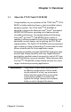
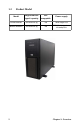
Chapter 1: Overview 1.1 About the TYAN Tank FT48-B5382 Congratulations on your purchase of the TYAN TankTM FT48B5382, a highly-optimized tower or rack-mountable (option) barebone system. The TYAN TankTM FT48-B5382 is designed to support the latest two Intel ® Xeon ® processors 5000/5100/5300 series, providing a rich feature set and incredible performance.
1.
1.3 Features Enclosure Front Panel Features • • • • • Industry 19” rack-mountable 4U & Pedestal convertible chassis (3) 5.25” Driver bays (8) 3.5” HDD bays Dimensions: -D 27.5 x W 16.8 x H 6.9 inch -D 700 x W 427 x H 176 mm • • Processors • Dual LGA771 sockets • Support up to two Intel® Dempsey / Woodcrest / Clovertown processors 1333/1066/667MT/s FSB VRD 11.
BIOS • • • • • • • • • • Phoenix BIOS® on 8Mbit Flash ROM Supports APM 1.2, ACPI 1.0b Serial Console Redirect PXE via Ethernet USB device boot PnP, DMI 2.0, WFM 2.
1.4 Unpacking This section describes the FT48-B5382 package contents and accessories.Open the box carefully and ensure that all components are present and undamaged. 1.4.1 Box Contents Component Description Industry standard 4U chassis with eight HDD bays and three further 5.
Component Description M1014 FAN control board (pre-installed) B5382FT48W8HR - 750W (2+1) redundant hot-swap PSU B5382FT48W8H - 700W single PSU (3) system cooling fans (pre-installed) 120 x 120 x 38 mm 6 Chapter 1: Overview
1.4.2 Accessories If any items are missing or appear damaged, contact your retailer or browse to TYAN’s Web site for service: http://www.tyan.com. The Web site also provides information on other TYAN products, plus FAQs, compatibility lists, BIOS settings, and more.
FDD Cable HDD Screws FDD Front Panel Security Tab (including two screws) 1 x 1394 cable 1 x DVD-ROM cable Sliding Rail Kit (Option) Rail assembly 2 x Mounting Ears (including six screws) Screws & Small Brackets 8 Chapter 1: Overview
1.5 About the Product This section contains hardware diagrams and a block diagram of the FT48-B5382 system. 1.5.1 System Front View and Front Panel See the diagram below for details of the front panel indicators and switches. Power button USB ports Reset button LAN2 LAN1 Power on HDD/IDE LED LED control panel DVD-ROM 5.
1.5.
On the rear of the FT48-B5382, two screw holes are available for you to secure the chassis lid with two screws. By default, the unit has no screws secured from the rear.
1.5.3 System Top View for FAN LEDs FAN3 LED LED FAN2 LED FAN1 LED Color FAN1/FAN2/FAN3 Description Green Fan is functioning normally. Red Fan fails. 1.5.4 LED Control Panel LED Power LED Color Red HDD/ IDE LED Green LAN LED State Description On System is turned on Off No mains power Blinking Internal SATA/ IDE access Off No disk activity Green On LAN is connected Green Blinking LAN is active Each LAN LED on the front panel corresponds to the onboard LAN port as listed below.
1.5.5 HDD Tray LEDs LED Color Hot Swappable HDD Power/ Access LED (Only for internal SAS port access) Hot Swappable HDD SAS Fail LED State Description Green ON Power connected Green Blinking SATAII/ SAS HDD access activity OFF Amber OFF ON Power disconnected SAS HDD fail (reserved for SAS add-on card) OFF OFF No failure found 1.5.
1.5.
1.5.
1.5.
1.5.10 System Internal View 1 5 6 2 7 8 3 9 10 11 4 12 1. Memory riser cards 2. CPU0 / CPU 1 sockets 3. System fans (Right to left): FAN1/2/3 4. Cradle for 5.25-inch devices 5. PCI / PCI-X / PCI-E slots 6. SAS ports Chapter 1: Overview 7. 8. 9. 10. 11. 12.
18 Chapter 1: Overview
Chapter 2: Chapter 2: Setting Up 2.1 Before You Begin This chapter explains how to install motherboard components, including CPUs, CPU heatsinks, memory modules, and PCI cards. There are also instructions in this section for installing SATA hard drives. Take note of the precautions mentioned in this section when installing your system. 2.1.1 Work Area Make sure you have a stable, clean working environment. Dust and dirt can get into components and cause malfunctions.
2.1.3 Precautions Components and electronic circuit boards can be damaged by discharges of static electricity. Working on a system that is connected to a power supply can be extremely dangerous. Follow the guidelines below to avoid damage to the Tank FT48-B5382 or injury to yourself. • Ground yourself properly before removing the top cover of the system. Unplug the power from the power supply and then touch a safely grounded object to release static charge (i.e. power supply case).
2.2 Installing Motherboard Components This section describes how to install components on to the motherboard, including CPUs, memory modules and expansion cards. 2.2.1 Removing the Chassis Cover Follow these instructions to remove the Tank FT48-B5382 chassis cover. This step is required before any other procedures in this chapter can be undertaken. 1. If the chassis lid is secured with two screws from the rear of the unit, remove them first. See “System Rear View” on page 10 for the screw locations. 2.
2.2.2 Installing the CPUs and Heatsinks This section describes how to install Intel Xeon processors and heatsinks on the FT48-B5382 motherboard. 1. Locate the two CPU sockets on the motherboard. 2. Take off the CPU protection cap. 3. Pull the CPU lever up to unlock the CPU socket.
4. Open the socket in the direction as illustrated. 5. Place the CPU in the socket as shown, making sure that pin 1 is located correctly. NOTE: The CPU will only fit in the socket one way. No force should be required to insert the CPU. 6. Close the socket cover to lock the CPU in place, and press the CPU lever down in the direction shown to secure the CPU.
7. Remove all packaging from the new heatsink. Place the fan and heatsink on top of the CPU and attach with four screws as shown. NOTE: All heatsinks must be installed with fans facing the rear of the chassis to ensure efficient cooling. 8. Attach the fan power cable to the CPU fan pin header on the motherboard as shown. See “Motherboard Layout” on page 14 for the fan header locations. 9. Repeat these steps to install the second CPU.
2.2.3 Installing the Memory Follow the instructions in this section to install memory modules in your FT48-B5382 system. 1. Locate the memory sockets on the memory riser cards. 2. Rotate the four press brackets as shown to release the memory riser card. 3. Lift the two memory riser cards from the FBDIMM riser socket.
4. Press the memory slot locking levers in the direction of the arrows as shown. 5. Insert the memory module into the slot. NOTE: Memory modules will fit in the slot only one way. Ensure that the notches in the memory modules line up with the corresponding notches in the slots. When inserted properly, the memory slot locking levers lock automatically onto the indentations at the ends of the module. Make sure that the memory module is seated firmly in place.
6. Insert the two memory riser cards into the socket as shown. 7. Install the four supplied press brackets in the direction of the arrow shown to fix the memory riser card. 8. Fasten the four press bracket screws as shown until firmly secured.
M5382 Layout Attention When Installing the Memory! Refer to the following table for supported memory populations. Quantity of memory installed DIMM1 1 2 X X 4 X 6 X X DIMM2 X X X X X DIMM3 Fully Buffered DIMM Riser Socket 0 8 DIMM6 X X X X X X X X DIMM8 X X DIMM2 Fully Buffered DIMM Riser Socket 1 X X X X X X X X DIMM7 DIMM1 X X DIMM4 DIMM5 16 X X X X X X X X X X X X X X X DIMM3 X DIMM4 X DIMM5 X DIMM6 X X X X X DIMM7 X DIMM8 X NOTE: 1.
2.2.4 Installing the PCI/PCI-X/PCI-E Cards The FT48-B5382 has seven expansion slots: 4 x PCI-X slots 2 x PCI-E x16 slots 1 x PCI slot Follow the instructions in this section to install a PCI card in your system. 1. Locate the PCI/PCI-X/PCI-E card slots on the motherboard. See “System Internal View” on page 17 for the PCI/PCI-X/PCI-E slot locations. 2. Unscrew the blanking plate from the slot you want to use.
3. Lift up the blanking plate. 4. Insert a PCI/PCI-X/PCI-E card into a spare slot as shown, making sure it is firmly seated. 5. Secure the PCI/PCI-X/PCI-E card with the screw you removed from the blanking plate.
2.3 Installing Hard Drives The FT48-B5382 supports eight, hot-swappable SAS/SATA hard drives. The unit is shipped with eight hot-swap bays and two SATA backplanes.
Follow these instructions to install a hard drive. 1. Press the release clip (A) and pull the release lever up to unlock the drive tray from the chassis (B). A B 2. Pull the empty drive tray from the chassis. 3. Place a SAS/SATA hard drive in the drive tray.
4. Secure the hard drive in place using four HDD screws. 5. Insert the drive tray back into the chassis and push the locking lever into place to secure it.
2.4 Installing the Second DVD-ROM (Option) Follow these instructions to install the second DVD-ROM. 1. Remove the FAN1 and FAN2 in the direction of the arrow from the chassis. 2. Unfasten an empty drive bracket from the chassis in the direction of the arrow shown. 3. Remove the two rails from the drive bracket.
4. Attach the two rails removed from the drive bracket to the DVD-ROM with eight screws. 5. Slide the DVD-ROM into the chassis. 6. Connect the power and DVD-ROM cables to the rear of the DVD-ROM drive.
2.5 Installing the Floppy Disk Drive (Option) Follow these instructions to install a floppy disk drive. 1. Remove all the fans in the direction of the arrow from the chassis. 2. Remove the two screws securing the fan cradle to the chassis. 3. Remove the fan cradle as instructed to reveal the fan control board.
4. Unfasten an empty drive bracket from the chassis in the direction of the arrow shown. 5. Use a thin tool such as a flat screwdriver to pry open the front panel of the drive bracket as indicated. 6. Remove the front panel and the inner piece as shown.
7. Install the FDD front panel to the front of the bracket. 8. Place a FDD in the drive bracket. 9. Secure the FDD in place using four screws.
10. Slide the FDD with the drive bracket back into the chassis. 11. Connect one end of the supplied FDD cable and the power cable to the rear of the FDD (A). Pass the other end through the space behind the metal plate as shown below (B). A B 12. Connect the other end of the FDD cable to the connector on the motherboard.
2.6 Installing Chassis Foot Stands The FT48-B5382 can be used as a standalone device when fitted with the supplied plastic feet. When used as a standalone device, the feet must be fitted to prevent the unit from falling over. The four feet should be attached as follows: 1. Each foot consists of two pieces. Insert the round piece of the foot into the larger foot section. The small plastic tab on the round piece should fit into the curved slot on the other piece. Curved slot Tab fits in curved slot 2.
2.7 Opening the Chassis Door 1. Insert the front door key (packed in a bag in the accessory box) and rotate the key 90 degrees counterclockwise to unlock the door. 2. Pull the door in the direction of the arrow to open.
2.8 Installing the Security Tab 1. Insert the supplied security tab into the security slot from the rear of the FT48-B5382 as shown below. 2. Secure the security tab with two screws. 3. Now you can lock the FT48-B5382 chassis with a padlock using the opening from the security tab.
Chapter 3: Replacing Pre-installed Components 3.1 Introduction This chapter describes how to replace all the pre-installed components of your FT48-B5382, including the motherboard, SATA backplane, LED control board, power supply, cooling fans, and fan control board. Take note of the precautions in this section when installing your system. 3.1.1 Work Area Make sure you have a stable, clean working environment. Dust and dirt can get into components and cause malfunctions.
3.1.3 Precautions Components and electronic circuit boards can be damaged by static electricity. Working on a system that is connected to a power supply can be extremely dangerous. Follow the guidelines below to avoid damage to the FT48-B5382 or injury to yourself. • Ground yourself properly before removing the top cover of the system. Unplug the power from your computer power supply and then touch a safely grounded object to release static charge (i.e. power supply case).
3.2 Disassembly Flowchart The following flowchart outlines the disassembly procedure. Rear Components DIMMs Single/ Redundant power Chassis top cover Heatsink/CPU assembly Mainboard PCI card Mainboard Front Components Chassis top cover DVD-ROM Control Board PCBs Fan Board FAN HDD Board Note: The Transport FT48-B5382 should be always powered off before disassembly.
3.3 Removing the Chassis Cover Follow these instructions to remove the Tank FT48-B5382 chassis cover. This step is required before any other procedures in this chapter can be undertaken. 1. Press the button on the release catch and lift the catch. Slide the chassis lid back slightly. 2. Lift the lid free from the chassis. Follow the steps above in reverse to refit the chassis cover.
3.4 Removing the Front Door Assembly A door is supplied with the FT48-B5382 that can be used when the unit is rack mounted or standalone. Follow these instructions to remove the door. 1. Pull out the four fixing bars locking the door assembly onto the server. 2. Remove the door assembly from the four holes located on the lower edge of the server. To replace the door assembly: 1. Tilt the door assembly and fit the four protruding tips into the holes located on the lower edge of the server. 2.
3.5 Replacing Motherboard Components Follow these instructions to remove motherboard components and replace the motherboard. 3.5.1 Disconnecting All Motherboard Cables Before replacing the motherboard or certain components, remove cables connected to the motherboard. Follow these instructions to remove all motherboard cabling. 1. Disconnect all the power cables. Main powerD EPS 12V power 2. Disconnect the DVD-ROM drive cable, SAS/SATA hard drive cables, USB cable, and front panel LED cables.
3. Disconnect the fan cables. 3.5.2 Replacing the Motherboard After removing all of those cables, follow these instructions to replace the motherboard in your FT48-B5382. 1. Remove the heatsinks and processors if installed. 2. Remove the nine screws securing the motherboard to the chassis. 3. Carefully lift the motherboard from the chassis. NOTE: The motherboard is fitted tightly into the chassis and will not lift straight out. You will need to lift one side of the board first and slide it out.
3.6 Replacing the Cooling Fans The FT48-B5382 requires three chassis cooling fans. Follow these instructions to replace a cooling fan. 1. Remove the fan in the direction of the arrow from the chassis. 2. Replace a new fan into the fan cradle following the above steps in reverse.
3.7 Replacing the Fan Control Board To replace the fan control board, you need to remove all the fans and the fan cradle first. Refer to the first three steps given in “2.5 Installing the Floppy Disk Drive (Option)”. Then, do the following: 1. Locate the system fan connectors on the motherboard. See “Motherboard Layout” on page 14 for the fan header locations. 2. Unplug the fan cable from the pin header on the motherboard. 3. Disconnect all the connector cables from the fan control board.
4. Remove the two screws securing the fixing brackets to the fan control board. 5. Remove the two fixing brackets as instructed for replacement of the fan control board. 6. Remove the ten screws securing the fan board to the chassis. 7. After replacement, install the fixing brackets and secure the fan cradle in place following the above steps in reverse.
3.7.
3.7.
3.8 Replacing the SAS/SATA Backplane To replace the SAS/SATA backplane, you need to remove all the fans and the fan cradle first. Refer to the first three steps given in “2.5 Installing the Floppy Disk Drive (Option)”. Then, do the following: 1. Remove all the SAS/SATA hot-swap HDD trays corresponding to the SAS/SATA backplane to be replaced from the FT48-B5382. 2. Disconnect all cables from the SATA/SAS backplane to be replaced. 3. Remove the screw holding the SATA/SAS backplane. 4.
3.8.
3.8.
3.9 Replacing the LED Control Board Follow these instructions to replace the LED control board. 1. Remove the FAN1 in the direction of the arrow from the chassis. 2. Remove all the cables from the LED control board. 3. Unfasten the LED module and slide it out as shown to lift it free of the chassis.
4. Remove the three screws securing the LED control board to the bracket. 5. Slide the LED control board from the bracket as shown. 6. After replacement, insert and secure the unit to the chassis following the above steps in reverse.
3.9.
3.9.
3.10 Replacing the DVD-ROM Follow these instructions to replace the DVD-ROM. 1. Remove the FAN1 and FAN2 in the direction of the arrow from the chassis. 1. Remove the power and DVD-ROM cables from the rear of the DVD-ROM drive. 2. Unfasten the DVD-ROM drive and slide it out of the chassis in the direction of the arrow shown.
3. Remove the eight screws securing the two DVD-ROM rails to the drive. 4. After replacement, insert the unit to the chassis following the above steps in reverse.
3.11 Replacing the Power Supply 3.11.1 Standard Power Supply To replace the power supply follow these instructions. 1. Unplug the power cable from the faulty power supply. 2. Remove the three screws that secure the power supply to the chassis. 3. Remove the five screws securing the power supply to the chassis. 4. Lift the power supply free from the chassis.
5. Pull out the power supply unit from its casing. 6. Remove the four screws securing the cover plate to the power supply unit. 7. After replacement, place and secure the unit into the chassis following the above steps in reverse. 3.11.2 Redundant Power Supply If the 2+1 redundant power supply is fitted, any of the three units can be hot swapped. Follow these instructions to replace a single power unit with a redundant power supply unit. 1.
2. Release the redundant power supply by turning thumb screw clockwise. 3. Press the latch and the handle together as shown. 4. Pull out the power supply unit as shown. 5. Place the unit with the new power supply unit and secure by tightening the thumb screw.
Appendix I: BIOS Differences The BIOS of B5382 is similar to the BIOS of S5382. There is only one menu different. You may refer to the attached motherboard manual for the complete BIOS information. The differences between B5382 and S5382 is on the “Advanced/Hardware Health Information” menu. See the following for the differences.
S5382 Advanced/Hardware Monitor Information PhoenixBIOS Setup Utility Advanced Fan Speed Control: Cpu Temp Reading: Front Fan 3pin/4pin Rear Fan 3pin/4pin X Realtime sensors F1 Esc Help Exit [Full Speed] [PECI] [4pin] [4pin] ÇÈ Select Item ÅÆ Select Menu Item Specific Help Select mode to control fan speed.
Appendix II: Cable Connection Tables SAS/SATA Cables Table 1: FT48-B5382 Model M1211 SAS/SATA Backplane 1 Connects to Motherboard J8 (HDD1) Æ SAS1 J7 (HDD2) Æ SAS2 J6 (HDD3) Æ SAS3 J5 (HDD4) Æ SAS4 M1211 SAS/SATA Backplane 2 Connects to Motherboard Æ SAS5~8 J8 (HDD5) J7 (HDD6) J6 (HDD7) J5 (HDD8) FAN Cables Table 2: System Fan to Motherboard System Fan Connects to Motherboard Fan 1 Æ P9 Fan 2 Æ P8 Fan 3 Æ P92 Power Supply Cables Table 3: Power Supply to Motherboard Power Sup
Table 3: Power Supply to Motherboard P2 8-pin power cable Æ PWR2 8-pin connector P3 8-pin power cable Æ PWR3 8-pin connector Table 4: Power Supply to Backplane Power Supply Connects to M1211 SAS/SATA Backplane 1 P9 4-pin power cable Æ J13 P8 4-pin power cable Æ J14 Power Supply Connects to M1211 SAS/SATA Backplane 2 P11 4-pin power cable Æ J13 P10 4-pin power cable Æ J14 Table 5: Power Supply to FAN Board Power Supply Connects to M1014 FAN Board P13 4-pin power cable Æ J1 P12 4
Other Cables Table 8: LED Control Board to Motherboard LED Control Board Connects to Motherboard USB connector Æ P93 Front panel header Æ JP16 JP31, JP32 Table 9: DVD-ROM Cable to Motherboard DVD-ROM Connects to Motherboard DVD-ROM 1 Æ IDE DVD-ROM 2 (option) Æ IDE Table 10: FDD Cable to Motherboard (Option) FDD Connects to Motherboard FDD drive Æ Floppy 71
Appendix III: Installing the SMDC Card (Option) The following provides you with the information on installing M3291 SMDC card into any PCI slot in your FT48-B5382 system. 1. Secure M3291 on a PCI bracket as shown. 2. Connect the following cables to M3291 as shown. a. 2x25 pin SMDC cable to M3291 J1 connector. b. 2x5 pin serial cable to M3291 COM port (J2). b a 3. Unscrew the blanking plate from the slot as shown. LifUnscrew the blanking plate from the slot as shown.
4. Lift up the blanking plate. 5. Connect the other end of SMDC cable and serial cable to the SMDC connector (J79) and COM header (J88) on the motherboard. 6. Place the SMDC card in the PCI slot as shown.
7. Secure the PCI bracket with the screw you removed from the blanking plate.
Appendix IV: Rack Mounting (Option) Installing the 5.25” Devices in Rackmount Position Before mounting the FT48-B5382 in a rack, you need to rotate all the drives to the rackmount position first. Follow the steps as instructed below. 1. Remove all the fans and the fan cradle first. Refer to the first three steps given in “2.5 Installing the Floppy Disk Drive (Option)”. 2. Disconnect all the cables from the devices placed in the 5.25” bays as shown. 3.
4. Slide all the drives or the brackets out of the chassis. 5. Slide all the drives or the brackets back into the chassis vertically. 6. Replace all the cables to the devices as shown.
7. Remove the front bezel from the door assembly and rotate it 90 degrees counterclockwise as shown. 8. Fit the front bezel back into position. 9. Now, all the drives and the front bezel are in the rackmount position.
Installing the Server in a Rack The Tank FT48-B5382 can either be set in a tower position using the supplied chassis foot stands or mounted in a standard rack using the sliding rail kit. Sliding rail kit (Option) Rail assembly x 2 Mounting Ears x 2 Screws Kit x 3 Follow these instructions to mount the FT48-B5382 into an industry standard 19" rack. NOTE: Before mounting the Tank FT48-B5382 in a rack, ensure that all internal components have been installed and that the unit has been fully tested.
Installing the Inner Rails to the Unit 1. Remove the black panels from the left and right sides of server to reveal the rail mounting screwholes beneath. 2. Screw the mounting ears to each side of the FT48-B5382 as shown using three M4-L5 screws (C) from the supplied screws kit. 3. Draw out the inner rails from each rail assembly. Install the inner sliding rails to each side of the server using five M4-L5 screws (C).
Installing the Outer Rails to the Rack 4. Measure the distance between inner side of the front and rear mounting brackets in the rack. 5. Adjust the outer rails to fit the length of the rack (the distance measured in step 4). The sliding brackets have long slits to allow them to be fixed to the other part of the rails in various positions. 6. Install the two small brackets (A) to each mounting bracket (front x 2, rear x 2) in the rack.
7. Secure the outer rails to the rack using four M6 screws (B) for each side. Secure the mounting brackets from outside, not inside, of the rack.
Rackmounting the Server 8. Draw out the middle rail to the latch position. 9. Lift the unit and then insert the inner slide rails into the middle rails. 10. Push the unit in and press the latch key.
11. Push the whole system into the rack. 12. Secure the mounting ears of the unit to the rack using two small brackets (A) and M6 screws (B). Notes: • When the rails are extended, they will lock. To shorten the rails again, you will need to operate the release mechanism in each rail. • To avoid injury, it is strongly recommended that two people lift the FT48-B5382 into the place while a third person screws it to the rack.
Technical Support If a problem arises with your system, you should first turn to your dealer for direct support. Your system has most likely been configured or designed by them and they should have the best idea of what hardware and software your system contains. Hence, they should be of the most assistance for you.
2. See the TYAN website for FAQ’s, bulletins, driver updates, and other information: http://www.tyan.com 3. Contact your dealer for help BEFORE calling TYAN. 4. Check the TYAN user group: alt.comp.periphs.mainboard.TYAN Returning Merchandise for Service During the warranty period, contact your distributor or system vendor FIRST for any product problems.
86