% % , 5 3 ( 5 3 ( 4 ! 3 2 - & + @ A ( 8 ? 3 $ 1 0 / ) ' ( . . ; > = : 9 ! < , + - , + * % ) ( ' " ! " ; ' ' 9 3 .
SAFETY NOTES m m m m m m IMPORTANT: PRIOR TO ANY ASSEMBLY Please Note: after removing kit from shipping box, lay each piece flat on a hard surface, this will allow the airframe to straighten out if lightly bent from shipping. Do not worry since EPP is very pliable and can be bent back if out of shape.
Q P N E E F O L M N G H D U H F J T F D S G T I F S Q D P N Q K K K R E E F O L M N G H H D F J J J J G H I E F D C D TWISTED HOBBYS Thank you for your purchasing a Twisted Hobbys‘ model. Please read through the entire manual before beginning to build this model. If you have any questions please contact us at the above indicated email address. WARNING INFORMATION This R/C Aircraft is not a toy! Read and understand the entire manual before assembly.
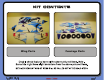
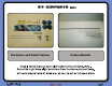
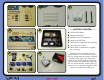
kit contents Fuselage Parts V Wing Parts
^ \ ] [ X Y Carbon Bundle W Hardware and Small Carbon Z kit contents
TOOL AND ADHESIVES NEEDED Lighter Small Drill Bits Tape Measure and Ruler Black Sewing Thread Welders or Foam Tac Glue Hobby Knife w/new Blade Needle Nose Pliers Wire Cutters Low Temp Hot Glue Gun Course Sand Paper Scissors Small Phillips Screw Driver Thin and Medium CA CA Applicator Tips Activator _
the build CONSTRUCTION METHODS: Building surface should be at least 2ft x 4ft and flat. Weights or some small heavy objects will be handy for holding things in place during the time glue is setting. Welders or FoamTac glue is used for FOAM TO FOAM joints. Thin and Medium CA can be used on the PLASTIC TO FOAM and CARBON TO FOAM joints. When using the Welders or FoamTac glue for a butt joint, apply a thin film to each surface, allow to sit breifly per mfg instructions, then assemble.
A B C D E ------ GETTING STARTED ------ G Control Rod Ends Push Rod Guides Landing Gear Components Radio and FPV Tray Small Parts Organized for Building Optional Power Combo Basic FPV Components supplied by Customer Identify all the components and pieces shown in the pictures. If there are any items missing contact Twisted Hobbys right away. If it looks like some of the small parts are missing, double check the hardware bags and kit box. Note that the items shown in picture G are customer supplied.
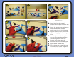
A B D E C ------ THE WING ------ F G Wipe it down with alcohol Test fit it into the reward slot on the bottom side of the wing and secure with thin CA b Gently bend all the control surfaces back and let them sit like this for about an hour Locate the two longest and largest spars,1x5x950mm, and the smaller one that is .
A B C D E ------ THE WING (con’t) -----Wipe down the two main spars with alcohol before fitting Test fit the rear main spar so that it is flush with the surface Install the rear main spar, pushing it flush to the wing surface for the how length F G Secure the wing and spars flush to the work bench with some weights Glue all the three of the spars to the wing with some thin CA, don't hit with kick yet Let the whole assembly sit for a couple minutes to all the CA to soak in, then hit with
A B C D E ------ THE WING (con’t) -----FoamTac or CA can be used to attach the control surface horns F G Adjust the length as needed Retest the fit Make sure the front of the horn is flush with the edge of the hinge cut Apply some glue to the base of the control horn Install into the slot, again making sure that the front edge of the horn is flush with the hinge cut.
------ MAIN FUSELAGE STRUCTURE / Before you Start -----If you are an experienced builder all the detail may not be necessary, if so skip ahead a couple pages. Building the Main Fuselage structure for the proXy will be similar to that of the Crack Beaver. There are a couple different ways to do this, method and sequence shown here will ensure that the X cross section of the fuselage will come out nice and square with little effort.
----- THE PROCESS / words (con’t) ----The next several steps will all be done WITHOUT GLUE it is for test fitting only and to understand how the assembly will go together, study the pictures and make sure everything fits together nicely Take the top half of the fuselage with the spars sticking out and feed those spar ends thru the cut outs in the fuselage Get it pretty close to the tabs, then focus your attention the the rear Ele/Rud spar and feed it thru its associated hole Fully engage all the tabs and sl
B D E C ------ MAIN FUSELAGE -----Pictures to follow along with for the previous two pages F G ...
B D E C ------ MAIN FUSELAGE (con’t) ------ G Using the “tack” method attache the two pieces Locate the shorter spars from the set pictured above (.
B D E C ------ MAIN FUSELAGE (con’t) ------ G ... test fit it, as was done with the other one Constrain and combined with CA and kicker Locate two of the four longer spars (.5x3x332mm long) Prep them Test fit them Make sure the go all the way up to the top of the slot near the wing saddle part of the fuselage F Locate the other short spar, prep it and ...
B D E C ------ MAIN FUSELAGE (con’t) ------ F G Compare the slots in the hub to the exposed spars The two should match up pretty close, if not double check to make sure the spar is up against the other end of the slot Constrain Flat and secure with thin CA and kicker Grab the remaining two spars (.
B D E F G C ------ MAIN FUSELAGE (con’t) ------ Use the “tack” method and attach the tail piece shown, only apply the glue on the foam-foam part of the joint Hold pressure for a minute or so Finished parts Secure the carbon-foam part of the joint with thin CA and kicker THIS IS WHERE TEST FITTING STARTS - DO NOT USE GLUE UNTIL CALLED FOR All the way thru... ....
B D E C ------ MAIN FUSELAGE (con’t) ------ F G Fully engage the tail tabs Fully engage the forward tabs Check that the fuselage saddle area is approximately level/horizontal Flip the fuselage assembly over so that the extended spars are facing upward Grab the mating lower fuselage section and start to line up the tabs into their cutouts and the spars into their slots You will have to fit them up to each other initially at a little bit of an angle, once the tabs and spars are nearly in
A B D E C ------ MAIN FUSELAGE (con’t) ------ F G Fully seat the spars land gear struts into their slots, make sure they are flush Check to make sure the two fuselage members are square to each other in and around the landing gear strut area Fully seat the tail spars into their slots, make sure they are flush Check to make sure the two fuselage members are square to each other in and around the tail section TEST FIT UP is essentially done, have a look at the whole thing and make sure
B D E C ------ MAIN FUSELAGE (con’t) ------ Feed the spars thru the tail section Apply glue to lower fuselage sections G Check for squareness and that all the joints are firm against each other Keep the two long extended spars free of glue at this time Keep the single extended tail spare free of glue as well Press all the FoamTac joints together firmly for a minute or two or until they hold their own position F Feed th
A B D E C ------ MAIN FUSELAGE (con’t) ------ F G Check that the fuselage is square all along the length nose to... ...
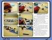
B D E C ------ WHEEL / AXLES/ HUBS ------ F G Locate the two 3D printed axle hubs, the socket head cap screws and the wood hub caps Separate the hubs from their wooden tree Take one of the hub caps, one of the cap screw and a solid wheel piece Fit them together, using the cap screw as a locator to position the hub cap at the center of the foam wheel piece. Secure with CA or FoamTac Flip the tire piece over... ...
B D E F G C ------ WHEEL / AXLES/ HUBS ------ Gather up all two of the donuts with holes in the center as pictured Apply some FoamTac to one side Repeat for the other wheel Once both wheels are built, put them under some heavy weights, and leave them there overnight, this will minimize the edges from curling up Locate the 3D printed axle hubs ...
B D E C ------ WHEEL / AXLES/ HUBS ------ F G Put some glue in the grooves Coat the spars Join the two pieces as shown and add a filet of glue all around the base of where the two pieces meet. Make sure the spars are flush and that the axle hub is firm against the bottom edge of the landing gear strut Repeat for the other side. Let this assembly dry at least overnight before attempting to attach the wheels Insert a cap screw thru the wheel and thread into the axle hub.
A C ------ TRUSSING ------ B D e d c f h d g Cut one of the 500mm long pieces into one each of: 121/105/98/88 mm long pieces Locate the slit cuts in the fuselage pieces that are angled to accept the ends of the rods just cut, fill each of the slots on one side with FoamTac Install the trussing as show, starting with the longest (thick one) that goes from the wing saddle down to the fuselage, from there they zig-zag towards the rear of the fuselage in decreasing size.
------ TAIL PUSH RODS AND SERVOS / Before you Start -----If you are an experienced builder all the detail may not be necessary, if so skip ahead a couple pages. Following is the process for the installation of the equipment tray, the dry fitting (no glue) of the servos, and the building (and installation) of the tail control rods. Read ahead a couple steps along the way if the assembly process is not clear on the current step. CAUTION SHOULD BE USED WHEN BUILDING THE CONTROL RODS.
------ COMPLETING THE PUSH ROD LENGTHS AND ENDS -----MAKE SURE THAT WHEN CALLED FOR THAT THE SERVOS ARE ELECTRONICALLY CENTERED AND THE CONTROL SURFACES ARE “LOCKED” IN THEIR NEUTRAL POSITIONS ------ THE PROCESS / words (con’t) ----- Center the servos Constrain the control surfaces to neutral Attach a clevis to one of the control surface horns, make sure the little brass pin gets snapped in all the a way.
B D E C ------ RADIO BAY -----** NOTE ** THE FOLLOW SEVERAL PAGES ARE THE PICTURES AND DESCRIPTIONS THAT GO WITH ALL THE VERBIAGE FROM THE PREVIOUS TWO PAGES F G Start by sanding the cross members smooth Test fit the tray and cross members together, do not glue at this time.
A B C ------ RADIO BAY (con’t) ------ Secure the main tray and cross members together with a drop of thin CA in the tabbed areas Secure the tray to the fuselage with thin CA where the tabs stick thru the foam. NOTE - you can leave these tabs “unglued” if you want a “removable” radio tray. It fits tight enough into the fuselage that glue is not necessary. Install the four servos as shown. Aileron servos near the wing saddle will be flush to the INSIDE, and their arms will face outward.
A B ------ TAIL HORNS ------ Locate the remaining two control horns. Note - All four control horns are exactly the same, so it does not matter which ones you use.
A B C ------ PUSH ROD GUIDES ------ Break them all apart. Note - they are all the same length and size. Stick one each into the pre-cut holes along the length of the fuselage boom. Note that they will be located on the TOP - INSIDE of the fuselage boom All guides installed.
A B C D E ------ TAIL CONTROL RODS ------ PART I F G Locate the two remaining .5x500mm rods Note that this build will use the clevis links on the control surface side of the control rod, and.... .... the ball link end will be used on the servo side of the control rod Grab two ball links and the white spacers Start the spacer into the end of the ball link Hold the assembly gently with a pair of needle nose or small pliers.
A B C D E ------ TAIL CONTROL RODS ------ PART I (con’t) G Note that there will be approx 1.5mm of exposed length of the white spacer as shown Test fit the control rod into the spacer, dress up the end a little if needed so that the rod will slide into the spacer ... and secure with some thin CA Repeat for the other control rod Slide it all the way in...
A B C D E ------ TAIL CONTROL RODS ------ PART I (con’t) F G Feed the free end of the control rod thru the guides starting with the ones closest to the servos Slide the rod all the way thru all the guides The ball link should line up pretty straight with the UNDER side of the servo control horn Manipulate the servo so that you can attach the ball link to the horn with it’s mating tiny screw.
A B C D E ------ TAIL CONTROL RODS ------ PART II F G Thread the brass part in approx as far as shown. This will give you a little adjustment in both directions if needed in the future Repeat for the other clevis ELECTRONICALLY CENTER THE TWO TAIL SERVOS LOCK THE CONTROL SURFACES IN THEIR NEUTRAL POSITION Grab one of the clevis assemblies just made... ... and attach it to the control surface horn with one of the little brass pins.
A B C D E ------ TAIL CONTROL RODS ------ PART II (con’t) F G You will want to shorten the control rod to a position that is just shy of where the threaded part starts Clip to length with a pair of cutter and dress up the end where it got crushed from the cutters Deflect the control surface away from it’s neutral position so that the end of the rod can be slid into the brass fitting Retrun the control surface to neutral, if needed shorten up the rod a little more With everything neutral,
A B ------ TAIL ROD GUIDES ------ CA the bases of the guides to the surrounding foam, but careful to avoid getting CA anywhere near the rod where it feeds thru the rod guide If you have a servo tester you can double check the centering and that there is no binding.
A B C D E ------ ATTACHING WING ------ F G There are reference marks (cuts) near the leading edge directly parallel with the inboard end of the ailerons reliefs These two marks will be used as guides when lining up the saddle area of the fuselage with the wing Lay the wing on your work bench, bottom side facing UP and test fit the fuselage The wing should be all the way forward until it is against the notch in the fuselage saddle... ...
A B C D E ------ ATTACHING WING -----(con’t) F G Wet glue method will be used to allow for minor adjustments as needed Flip the fuselage over and line it up with the forward notch and reference marks as when test fit Long push pins can be used to hold the two pieces in their exact position Make sure the edges line up perfectly Put some weights on the wings to keep everything nice and flat Brace up the tail as shown to keep the boom parallel Take some measurements from each wing tip t
B D E C ------ AILERON CONTROL RODS ------ F G Detail view of the items need for this step The clevis end and brass part will be the two screwed together Thread the brass part in approx as far as shown Repeat for the other clevis, then set these two aside for now Grab one of the ball links and test fit it onto one end of the rod.
A B ------ AILERON CONTROL RODS (con’t) ------ C Attach the ball link end to the aileron control horn, use a little thread locker on the screw. Make sure the aileron is in it’s neutral position and that the servo is electronically center. Attach the clevis and pin to the outer most hole of the servo control arm. Next trim the rod approx where shown with the red dashed line Dress up the end of the rod as needed after cutting so that it will slide into the brass fitting.
A B D E C ------ MOTOR MOUNT ------ F G Gather up the pieces shown Apply some FoamTac to the all white underside piece... ... and position as shown into it’s respective slots Apply some FoamTac to the upper color printed part... ... and position as shown into it’s respective slots on the top side of the wing Apply some FoamTac to one side of the motor mount... ...
B D E C ------ WINGLETS ------ F G Apply some FoamTac into the two BEVELED cut areas Position the winglet as shown up against a vertical surface and secure so that the glue can dry and hold the winglet in this position Repeat for the other winglet Let the glue completely dry before handling.
A B NOSE CENTER OF GRAVITY ------ ELECTRONICS -----MOTOR TAIL D Gather up the motor and mounting hardware Attach the X mount to the back side of the motor. Use thread locker If you are using the Twisted Hobbys’ motor and universal X mount, you will attach the mount with two screws to the holes that match up to the motor k t r r l p p p m l k s q o n q q o o n o n j w C Start by locating the Center of Gravity point for this airframe.
B C ------ ELECTRONICS MOTOR D ------ The motor will mount to the wood firewall as shown, with the motor wires pointing down, either to the left or right side If you are using the Twisted Hobbys’ motor, enlarge the holes in the wood mount with a 1/16” diameter drill, this will keep the wood from splitting. If you are using another motor and mounting hardware, you may or may not need to size the holes.
A B D E C ------ ELECTRONICS -----RX & FPV There are many, many different options available for setting this airframe up with receivers, flight controllers, FPV cameras and HD recording potential. What is shown here is just one possible solution. This gear is simple and easy to setup and will have you flying FPV without a bunch of programing or wiring.
Find yourself a park that is out of the way and full of spaced out trees or other obstacles, strap on the goggles and go..!! This completes the build, it’s design and construction should give you many hours of flying enjoyment. This airplane will serve you well, whether you are new to FPV flying or are a seasoned veteran. Please visit www.TwistedHobbys.com for other accessories and aircraft.
center of gravity and control throws NOSE CENTER OF GRAVITY TAIL C.G. - 2.375” from LE of wing k t r r l p p p m l k s q o n q q o o n o n j u w Locate all the electronics to achieve indicated CG point. Use Velcro for initial flights for battery mounting and experiment with it’s position until you have determined the best spot for your flying style.
pre-flight & testing Prefight Checks Prefight Checks Storage k t r r l p p p m l k s q o n q q o o n o n j o x Be safe and enjoy, thank you again for purchasing a Twisted Hobbys’ Product!
TIPS AND TRICKS A good building surface is — drop ceiling“ panel from a local hardware store on a nice flat board Use parchment paper between the areas being glued and your work surface Heavy flat objects (like books, batteries, etc.) could be used to hold everything flat When resetting your radio, start with all the ATV‘s or throw volumes at 100%. Make sure you have set the direction of the servos correctly before attempting to trim for zero position.
p p p r l m l k r k t s q o n q q o o n o n j n x notes and s/u Sheet