
User guide
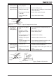
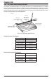


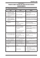


Table Of Contents
- 0-5143-CCr
- SECTION 1: ARC WELDING SAFETY INSTRUCTIONS AND WARNINGS
- SECTION 2: INTRODUCTION
- SECTION 3: INSTALLATION, OPERATION AND SETUP
- 3.01 Environment
- 3.02 Location
- 3.03 Ventilation
- 3.04 Mains Supply Voltage Requirements
- 3.05 Electromagnetic Compatibility
- 3.06 Transtig 170Pi Power Source Controls, Indicators and Features
- 3.07 Shielding Gas Regulator Operating Instructions
- 3.08 Setup for TIG (GTAW) Welding
- 3.09 Foot Control Part No. W4015800 (Optional Accessory)
- 3.10 Setup for Manual Arc (MMAW) Welding
- SECTION 4: BASIC WELDING GUIDE
- SECTION 5: POWER SOURCE PROBLEMS AND ROUTINE SERVICE REQUIREMENTS
- SECTION 6: KEY SPARE PARTS
- APPENDIX: TRANSTIG 170Pi CIRCUIT DIAGRAM
- CIGWELD - LIMITED WARRANTY TERMS
- TERMS OF WARRANTY – January 2013
- WARRANTY SCHEDULE – January 2013
- GLOBAL CUSTOMER SERVICE CONTACT INFORMATION
- SECTION 1: ARC WELDING SAFETY INSTRUCTIONS AND WARNINGS
- SECTION 2: INTRODUCTION
- SECTION 3: INSTALLATION, OPERATION AND SETUP
- 3.01 Environment
- 3.02 Location
- 3.03 Ventilation
- 3.04 Mains Supply Voltage Requirements
- 3.05 Electromagnetic Compatibility
- 3.06 Transmig 175i Power Source Controls, Indicators and Features
- 3.14 Shielding Gas Regulator Operating Instructions
- 3.17 Setup for TIG (GTAW) Welding
- 3.18 Setup for Manual Arc (MMAW) Welding
- SECTION 4: BASIC WELDING GUIDE
- SECTION 5: POWER SOURCE PROBLEMS AND ROUTINE SERVICE REQUIREMENTS
- AP0-5143-APENDIX
- CIGWELD - LIMITED WARRANTY TERMS
- TERMS OF WARRANTY - JULY 2010
- WARRANTY SCHEDULE - JULY 2010
- GLOBAL CUSTOMER SERVICE CONTACT INFORMATION

TRANSTIG 170Pi
POWER SOURCE PROBLEMS AND ROUTINE SERVICE REQUIREMENTS 5-2 Manual 0-5241
10 Fault light is on, and E-1 is
shown on the Amps display
A Fail to Safe protection has
operated in STICK mode-
VRD fault.
A Reset mains power, if fault does not
clear then have an accredited CIG-
WELD service provider repair unit.
B Fail to Safe protection has
operated in TIG mode- In-
verter fault.
B Reset mains power, if fault does not
clear then have an accredited CIG-
WELD service provider repair unit.
C External voltage has been
applied to the welding
circuit.
C Reset mains power and remove the
source of the external voltage.
Table 5-1
5.02 Routine Service and Calibration Requirements
!
WARNING
There are extremely dangerous voltage and power levels present inside this Inverter Power Source.
Do not attempt to open or repair unless you are an accredited CIGWELD Service Provider. Discon-
nect the Welding Power Source from the Mains Supply Voltage before disassembling.
Routine Inspection, Testing & Maintenance
The inspection and testing of the power source and associated accessories shall be carried out in accordance
with Section 5 of AS 1674.2 - 2007: Safety in Welding and Allied Processes-Part 2 Electrical. This includes an
insulation resistance test and an earthing test to ensure the integrity of the unit is compliant with Cigweld's
original specifications.
If equipment is to be used in a hazardous location or environments with a high risk of electrocution as outlined
in AS 1674.2 - 2007, then the above tests should be carried out prior to entering this location.
A. Testing Schedule
1. For transportable equipment, at least once every 3 months; and
2. For fixed equipment, at least once every 12 months.
The owners of the equipment shall keep a suitable record of the periodic tests and a system of tagging,
including the date of the most recent inspection.
A transportable power source is deemed to be any equipment that is not permanently connected and fixed
in the position in which it is operated.
B. Insulation Resistance
Minimum insulation resistance for in-service Cigweld Inverter Power Sources shall be measured at a voltage
of 500V between the parts referred to in Table 6-1below. Power sources that do not meet the insulation
resistance requirements set out below shall be withdrawn from service and not returned until repairs have
been performed such that the requirements outlined below are met.