
User guide
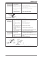
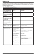


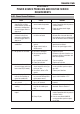


Table Of Contents
- 0-5143-CCr
- SECTION 1: ARC WELDING SAFETY INSTRUCTIONS AND WARNINGS
- SECTION 2: INTRODUCTION
- SECTION 3: INSTALLATION, OPERATION AND SETUP
- 3.01 Environment
- 3.02 Location
- 3.03 Ventilation
- 3.04 Mains Supply Voltage Requirements
- 3.05 Electromagnetic Compatibility
- 3.06 Transtig 170Pi Power Source Controls, Indicators and Features
- 3.07 Shielding Gas Regulator Operating Instructions
- 3.08 Setup for TIG (GTAW) Welding
- 3.09 Foot Control Part No. W4015800 (Optional Accessory)
- 3.10 Setup for Manual Arc (MMAW) Welding
- SECTION 4: BASIC WELDING GUIDE
- SECTION 5: POWER SOURCE PROBLEMS AND ROUTINE SERVICE REQUIREMENTS
- SECTION 6: KEY SPARE PARTS
- APPENDIX: TRANSTIG 170Pi CIRCUIT DIAGRAM
- CIGWELD - LIMITED WARRANTY TERMS
- TERMS OF WARRANTY – January 2013
- WARRANTY SCHEDULE – January 2013
- GLOBAL CUSTOMER SERVICE CONTACT INFORMATION
- SECTION 1: ARC WELDING SAFETY INSTRUCTIONS AND WARNINGS
- SECTION 2: INTRODUCTION
- SECTION 3: INSTALLATION, OPERATION AND SETUP
- 3.01 Environment
- 3.02 Location
- 3.03 Ventilation
- 3.04 Mains Supply Voltage Requirements
- 3.05 Electromagnetic Compatibility
- 3.06 Transmig 175i Power Source Controls, Indicators and Features
- 3.14 Shielding Gas Regulator Operating Instructions
- 3.17 Setup for TIG (GTAW) Welding
- 3.18 Setup for Manual Arc (MMAW) Welding
- SECTION 4: BASIC WELDING GUIDE
- SECTION 5: POWER SOURCE PROBLEMS AND ROUTINE SERVICE REQUIREMENTS
- AP0-5143-APENDIX
- CIGWELD - LIMITED WARRANTY TERMS
- TERMS OF WARRANTY - JULY 2010
- WARRANTY SCHEDULE - JULY 2010
- GLOBAL CUSTOMER SERVICE CONTACT INFORMATION

TRANSTIG 170Pi
Manual 0-5241 5-1 POWER SOURCE PROBLEMS AND ROUTINE SERVICE REQUIREMENTS
SECTION 5:
POWER SOURCE PROBLEMS AND ROUTINE SERVICE
REQUIREMENTS
5.01 Power Source Problems
FAULT CAUSE REMEDY
1 Mains supply voltage is ON,
Amps Display is illumi-
nated however unit will not
commence welding when
the torch trigger switch is
depressed.
A Power source is not in the
correct mode of operation.
A Set the power source to the correct
mode of operation with the process
selection switch.
B Faulty torch trigger. B Repair or replace torch trigger
switch/lead.
2 Fault Indicator is illumi-
nated and unit will not
commence welding when
the torch trigger switch is
depressed.
Duty cycle of power source
has been exceeded.
Leave the power source switched
ON and allow it to cool. Note that
fault indicator must be extinguished
prior to commencement of welding.
3 Welding arc cannot be
established.
A Poor or no work lead
contact.
A Clean work clamp area and ensure
good electrical contact.
B Trigger switch faulty or
disconnected.
B Connect or repair trigger switch.
4 No gas flow in TIG mode. A Gas hose is damaged. A Replace or repair.
B Gas passage contains
impurities.
B Disconnect gas hose from the rear
of power source or wirefeeder and
blow out impurities.
C Gas regulator turned off. C Turn on regulator.
D Empty gas cylinder. D Replace gas cylinder.
5 Gas flow continues after
the torch trigger switch has
been released (TIG mode).
A Gas valve has jammed open
due to impurities in the gas
or the gas line.
A Have an accredited CIGWELD
service provider repair or replace
gas valve.
B Post flow is active in TIG
modes.
B Reduce post flow time
6 Amps Display will not il-
luminate and welding arc
cannot be established.
The mains supply voltage
has exceeded voltage limits
of the power source.
Ensure that the mains supply volt-
age is within 240VAC ± 15%.
7 TIG electrode melts when
arc is struck.
TIG torch is connected to
the (+) VE terminal.
Connect the TIG torch to the (-) VE
terminal.
8 Arc flutters during TIG
welding.
Tungsten electrode is too
large for the welding cur-
rent.
Select the correct size of tungsten
electrode. Refer to Table 4-3.
9 No HF on the welding
output
A HF TIG mode is not selected A Set the power source to HF TIG
mode of operation with the process
selection switch.
B Faulty HF pcb. B Have an accredited CIGWELD
service provider repair or replace
the HF pcb.