
User guide
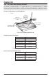
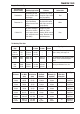


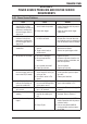


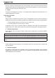
Table Of Contents
- 0-5143-CCr
- SECTION 1: ARC WELDING SAFETY INSTRUCTIONS AND WARNINGS
- SECTION 2: INTRODUCTION
- SECTION 3: INSTALLATION, OPERATION AND SETUP
- 3.01 Environment
- 3.02 Location
- 3.03 Ventilation
- 3.04 Mains Supply Voltage Requirements
- 3.05 Electromagnetic Compatibility
- 3.06 Transtig 170Pi Power Source Controls, Indicators and Features
- 3.07 Shielding Gas Regulator Operating Instructions
- 3.08 Setup for TIG (GTAW) Welding
- 3.09 Foot Control Part No. W4015800 (Optional Accessory)
- 3.10 Setup for Manual Arc (MMAW) Welding
- SECTION 4: BASIC WELDING GUIDE
- SECTION 5: POWER SOURCE PROBLEMS AND ROUTINE SERVICE REQUIREMENTS
- SECTION 6: KEY SPARE PARTS
- APPENDIX: TRANSTIG 170Pi CIRCUIT DIAGRAM
- CIGWELD - LIMITED WARRANTY TERMS
- TERMS OF WARRANTY – January 2013
- WARRANTY SCHEDULE – January 2013
- GLOBAL CUSTOMER SERVICE CONTACT INFORMATION
- SECTION 1: ARC WELDING SAFETY INSTRUCTIONS AND WARNINGS
- SECTION 2: INTRODUCTION
- SECTION 3: INSTALLATION, OPERATION AND SETUP
- 3.01 Environment
- 3.02 Location
- 3.03 Ventilation
- 3.04 Mains Supply Voltage Requirements
- 3.05 Electromagnetic Compatibility
- 3.06 Transmig 175i Power Source Controls, Indicators and Features
- 3.14 Shielding Gas Regulator Operating Instructions
- 3.17 Setup for TIG (GTAW) Welding
- 3.18 Setup for Manual Arc (MMAW) Welding
- SECTION 4: BASIC WELDING GUIDE
- SECTION 5: POWER SOURCE PROBLEMS AND ROUTINE SERVICE REQUIREMENTS
- AP0-5143-APENDIX
- CIGWELD - LIMITED WARRANTY TERMS
- TERMS OF WARRANTY - JULY 2010
- WARRANTY SCHEDULE - JULY 2010
- GLOBAL CUSTOMER SERVICE CONTACT INFORMATION
TRANSTIG 170Pi
BASIC WELDING GUIDE 4-14 Manual 0-5241
4.03 TIG (GTAW) Basic Welding Technique
Gas Tungsten Arc Welding (GTAW) or TIG (Tungsten Inert Gas) as it is commonly referred to, is a welding
process in which fusion is produced by an electric arc that is established between a single tungsten (non-
consumable) electrode and the work piece. Shielding is obtained from a welding grade shielding gas or welding
grade shielding gas mixture which is generally Argon based. A filler metal may also be added manually in some
circumstances depending on the welding application.
Welds Made With or Without
Addition of Filler Metal
Work Piece
Can Be Any Commercial
Metal
Gas Cup
Either Ceramic,
High-lmpact or
Water Cooled
Metal
Inert Gas
Shields Electrode
and Weld Puddle
Tungsten Electrode
Non-Consumable
A-09658_AB
Figure 4-28: TIG Welding Application Shot
Tungsten Electrode Current Ranges
Electrode Diameter DC Current (Amps)
0.040” (1.0mm) 30-60
1/16” (1.6mm) 60-115
3/32” (2.4mm) 100-165
1/8” (3.2mm) 135-200
5/32” (4.0mm) 190-280
3/16” (4.8mm) 250-340
Table 4-3: Current Ranges for Various Tungsten Electrode Sizes
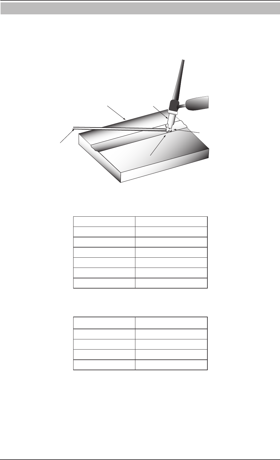
Guide for Selecting Filler Wire Diameter
Filler Wire Diameter DC Current Range (Amps)
1/16” (1.6mm) 20-90
3/32” (2.4mm) 65-115
1/8” (3.2mm) 100-165
3/16” (4.8mm) 200-350
Table 4-4: Filler Wire Selection Guide