
User guide
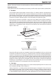
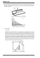


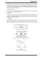


Table Of Contents
- 0-5143-CCr
- SECTION 1: ARC WELDING SAFETY INSTRUCTIONS AND WARNINGS
- SECTION 2: INTRODUCTION
- SECTION 3: INSTALLATION, OPERATION AND SETUP
- 3.01 Environment
- 3.02 Location
- 3.03 Ventilation
- 3.04 Mains Supply Voltage Requirements
- 3.05 Electromagnetic Compatibility
- 3.06 Transtig 170Pi Power Source Controls, Indicators and Features
- 3.07 Shielding Gas Regulator Operating Instructions
- 3.08 Setup for TIG (GTAW) Welding
- 3.09 Foot Control Part No. W4015800 (Optional Accessory)
- 3.10 Setup for Manual Arc (MMAW) Welding
- SECTION 4: BASIC WELDING GUIDE
- SECTION 5: POWER SOURCE PROBLEMS AND ROUTINE SERVICE REQUIREMENTS
- SECTION 6: KEY SPARE PARTS
- APPENDIX: TRANSTIG 170Pi CIRCUIT DIAGRAM
- CIGWELD - LIMITED WARRANTY TERMS
- TERMS OF WARRANTY – January 2013
- WARRANTY SCHEDULE – January 2013
- GLOBAL CUSTOMER SERVICE CONTACT INFORMATION
- SECTION 1: ARC WELDING SAFETY INSTRUCTIONS AND WARNINGS
- SECTION 2: INTRODUCTION
- SECTION 3: INSTALLATION, OPERATION AND SETUP
- 3.01 Environment
- 3.02 Location
- 3.03 Ventilation
- 3.04 Mains Supply Voltage Requirements
- 3.05 Electromagnetic Compatibility
- 3.06 Transmig 175i Power Source Controls, Indicators and Features
- 3.14 Shielding Gas Regulator Operating Instructions
- 3.17 Setup for TIG (GTAW) Welding
- 3.18 Setup for Manual Arc (MMAW) Welding
- SECTION 4: BASIC WELDING GUIDE
- SECTION 5: POWER SOURCE PROBLEMS AND ROUTINE SERVICE REQUIREMENTS
- AP0-5143-APENDIX
- CIGWELD - LIMITED WARRANTY TERMS
- TERMS OF WARRANTY - JULY 2010
- WARRANTY SCHEDULE - JULY 2010
- GLOBAL CUSTOMER SERVICE CONTACT INFORMATION
TRANSTIG 170Pi
BASIC WELDING GUIDE 4-12 Manual 0-5241
4.02 Stick (MMAW) Welding Troubleshooting
FAULT CAUSE REMEDY
1 Welding current
varying
ARC FORCE is set at a val-
ue that causes the welding
current to vary excessively
with the arc length.
Reduce the ARC FORCE until welding current is
reasonably constant while prohibiting the elec-
trode from sticking to the work piece when you
“dig” the electrode into the workpiece.
2 A gap is left by
failure of the weld
metal to fill the
root of the weld.
A Welding current too low A Increase welding current.
B Electrode too large for
joint.
B Use smaller diameter electrode.
C Insufficient gap. C Allow wider gap.
3 Non-metallic par-
ticles are trapped
in the weld metal.
A Non-metallic particles may
be trapped in undercut
from previous run.
A If a bad undercut is present clean slag out and
cover with a run from a smaller gauge electrode.
B Joint preparation too
restricted.
B Allow for adequate penetration and room for
cleaning out the slag.
C Irregular deposits allow
slag to be trapped.
C If very bad, chip or grind out irregularities.
D Lack of penetration with
slag trapped beneath weld
bead.
D Use smaller electrode with sufficient current to
give adequate penetration. Use suitable tools to
remove all slag from comers.
E Rust or mill scale is pre-
venting full fusion.
E Clean joint before welding.
F Wrong electrode for posi-
tion in which welding is
done.
F Use electrodes designed for position in which
welding is done, otherwise proper control of slag
is difficult.
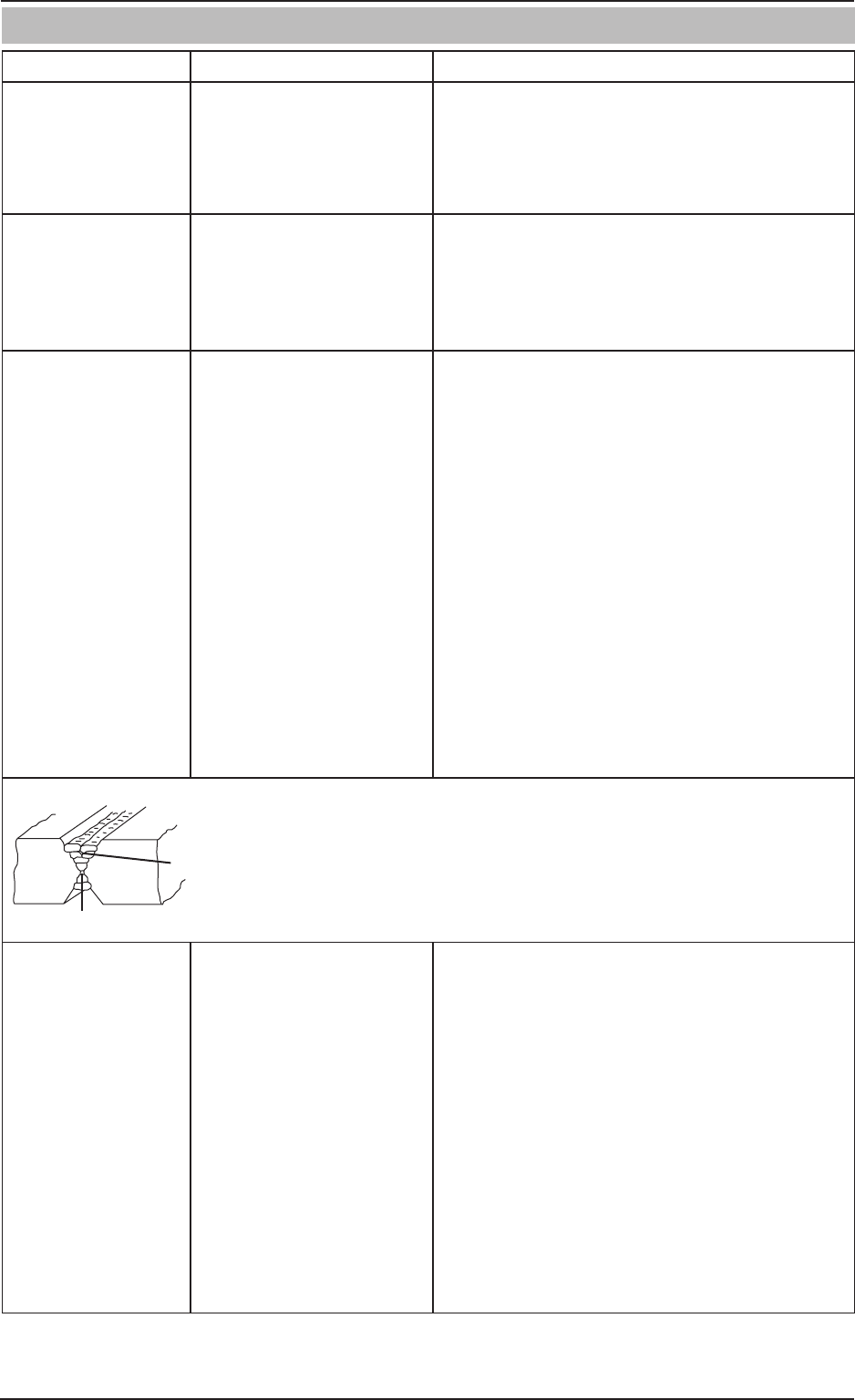
Insufficient Gap
Incorrect Sequence
Art # A-05866_AC
Figure 1-Example of insufficient gap or incorrect sequence
4 A groove has been
formed in the base
metal adjacent to
the toe of a weld
and has not been
filled by the weld
metal (undercut).
A Welding current is too
high.
A Reduce welding current.
B Welding arc is too long. B Reduce the length of the welding arc.
C Angle of the electrode is
incorrect.
C Electrode should not be inclined less than 45° to
the vertical face.
D Joint preparation does not
allow correct electrode
angle.
D Allow more room in joint for manipulation of the
electrode.
E Electrode too large for
joint.
E Use smaller gauge electrode.
F Insufficient deposit time at
edge of weave.
F Pause for a moment at edge of weave to allow
weld metal buildup.