
User guide
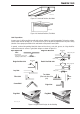
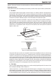
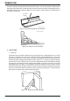


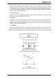


Table Of Contents
- 0-5143-CCr
- SECTION 1: ARC WELDING SAFETY INSTRUCTIONS AND WARNINGS
- SECTION 2: INTRODUCTION
- SECTION 3: INSTALLATION, OPERATION AND SETUP
- 3.01 Environment
- 3.02 Location
- 3.03 Ventilation
- 3.04 Mains Supply Voltage Requirements
- 3.05 Electromagnetic Compatibility
- 3.06 Transtig 170Pi Power Source Controls, Indicators and Features
- 3.07 Shielding Gas Regulator Operating Instructions
- 3.08 Setup for TIG (GTAW) Welding
- 3.09 Foot Control Part No. W4015800 (Optional Accessory)
- 3.10 Setup for Manual Arc (MMAW) Welding
- SECTION 4: BASIC WELDING GUIDE
- SECTION 5: POWER SOURCE PROBLEMS AND ROUTINE SERVICE REQUIREMENTS
- SECTION 6: KEY SPARE PARTS
- APPENDIX: TRANSTIG 170Pi CIRCUIT DIAGRAM
- CIGWELD - LIMITED WARRANTY TERMS
- TERMS OF WARRANTY – January 2013
- WARRANTY SCHEDULE – January 2013
- GLOBAL CUSTOMER SERVICE CONTACT INFORMATION
- SECTION 1: ARC WELDING SAFETY INSTRUCTIONS AND WARNINGS
- SECTION 2: INTRODUCTION
- SECTION 3: INSTALLATION, OPERATION AND SETUP
- 3.01 Environment
- 3.02 Location
- 3.03 Ventilation
- 3.04 Mains Supply Voltage Requirements
- 3.05 Electromagnetic Compatibility
- 3.06 Transmig 175i Power Source Controls, Indicators and Features
- 3.14 Shielding Gas Regulator Operating Instructions
- 3.17 Setup for TIG (GTAW) Welding
- 3.18 Setup for Manual Arc (MMAW) Welding
- SECTION 4: BASIC WELDING GUIDE
- SECTION 5: POWER SOURCE PROBLEMS AND ROUTINE SERVICE REQUIREMENTS
- AP0-5143-APENDIX
- CIGWELD - LIMITED WARRANTY TERMS
- TERMS OF WARRANTY - JULY 2010
- WARRANTY SCHEDULE - JULY 2010
- GLOBAL CUSTOMER SERVICE CONTACT INFORMATION
TRANSTIG 170Pi
Manual 0-5241 4-9 BASIC WELDING GUIDE
B. Distribution of Stresses
Distortion may be reduced by selecting a welding sequence which will distribute the stresses suitably so
that they tend to cancel each other out. See Figures 4-20 through 4-23 for various weld sequences. Choice
of a suitable weld sequence is probably the most effective method of overcoming distortion, although an
unsuitable sequence may exaggerate it. Simultaneous welding of both sides of a joint by two welders is
often successful in eliminating distortion.
C. Restraint of Parts
Forcible restraint of the components being welded is often used to prevent distortion. Jigs, positions, and
tack welds are methods employed with this in view.
D. Presetting
It is possible in some cases to tell from past experience or to find by trial and error (or less frequently, to
calculate) how much distortion will take place in a given welded structure. By correct pre-setting of the
components to be welded, constructional stresses can be made to pull the parts into correct alignment.
A simple example is shown in Figure 4-21.
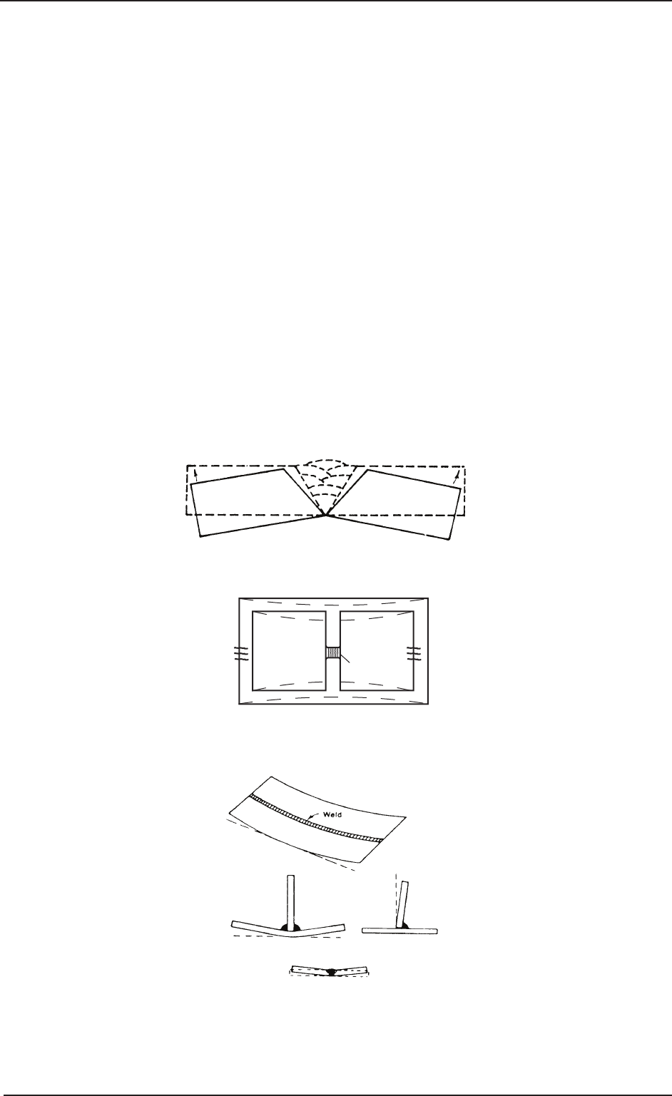
E. Preheating
Suitable preheating of parts of the structure other than the area to be welded can be sometimes used to
reduce distortion. Figure 4-22 shows a simple application. By removing the heating source from b and c as
soon as welding is completed, the sections b and c will contract at a similar rate, thus reducing distortion.
Art # A-07707
Figure 4-21: Principle of Presetting
Art # A-07708
B
PreheatPreheat
Dotted lines show effect if no preheat is used
Weld
C
Figure 4-22: Reduction of Distortion by Preheating
Art # A-07709
Figure 4-23: Examples of Distortion