
User guide
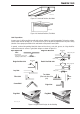
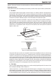
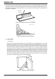


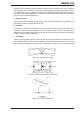


Table Of Contents
- 0-5143-CCr
- SECTION 1: ARC WELDING SAFETY INSTRUCTIONS AND WARNINGS
- SECTION 2: INTRODUCTION
- SECTION 3: INSTALLATION, OPERATION AND SETUP
- 3.01 Environment
- 3.02 Location
- 3.03 Ventilation
- 3.04 Mains Supply Voltage Requirements
- 3.05 Electromagnetic Compatibility
- 3.06 Transtig 170Pi Power Source Controls, Indicators and Features
- 3.07 Shielding Gas Regulator Operating Instructions
- 3.08 Setup for TIG (GTAW) Welding
- 3.09 Foot Control Part No. W4015800 (Optional Accessory)
- 3.10 Setup for Manual Arc (MMAW) Welding
- SECTION 4: BASIC WELDING GUIDE
- SECTION 5: POWER SOURCE PROBLEMS AND ROUTINE SERVICE REQUIREMENTS
- SECTION 6: KEY SPARE PARTS
- APPENDIX: TRANSTIG 170Pi CIRCUIT DIAGRAM
- CIGWELD - LIMITED WARRANTY TERMS
- TERMS OF WARRANTY – January 2013
- WARRANTY SCHEDULE – January 2013
- GLOBAL CUSTOMER SERVICE CONTACT INFORMATION
- SECTION 1: ARC WELDING SAFETY INSTRUCTIONS AND WARNINGS
- SECTION 2: INTRODUCTION
- SECTION 3: INSTALLATION, OPERATION AND SETUP
- 3.01 Environment
- 3.02 Location
- 3.03 Ventilation
- 3.04 Mains Supply Voltage Requirements
- 3.05 Electromagnetic Compatibility
- 3.06 Transmig 175i Power Source Controls, Indicators and Features
- 3.14 Shielding Gas Regulator Operating Instructions
- 3.17 Setup for TIG (GTAW) Welding
- 3.18 Setup for Manual Arc (MMAW) Welding
- SECTION 4: BASIC WELDING GUIDE
- SECTION 5: POWER SOURCE PROBLEMS AND ROUTINE SERVICE REQUIREMENTS
- AP0-5143-APENDIX
- CIGWELD - LIMITED WARRANTY TERMS
- TERMS OF WARRANTY - JULY 2010
- WARRANTY SCHEDULE - JULY 2010
- GLOBAL CUSTOMER SERVICE CONTACT INFORMATION
TRANSTIG 170Pi
BASIC WELDING GUIDE 4-6 Manual 0-5241
from the vertical. Some electrodes require to be sloped about 20º away from the perpendicular position
to prevent slag from running ahead of the weld. Refer to Figure 4-13. Do not attempt to build up much
larger than 6.4mm width with a 3.2mm electrode, otherwise the weld metal tends to sag towards the base,
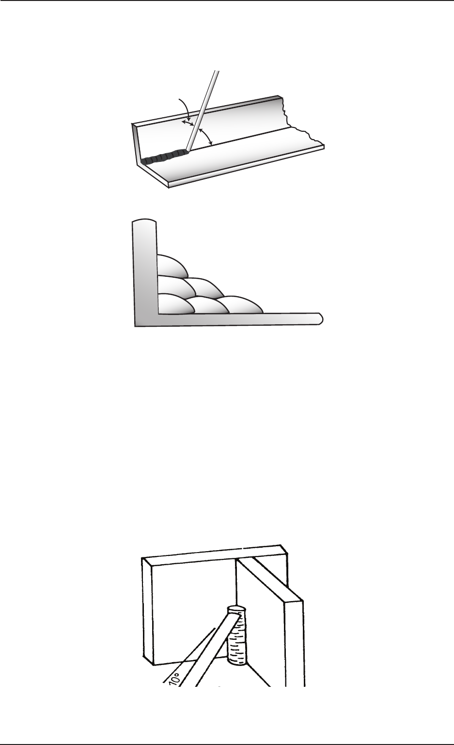
and undercut forms on the vertical leg. Multi-runs can be made as shown in Figure 4-14. Weaving in HV
fillet welds is undesirable.
Art # A-07699_AB
45° from
vertical
60° - 70° from line
of weld
Figure 4-13: Electrode Position for HV Fillet Weld
Art # A-07700_AB
1
2
3
4
5
6
Figure 4-14: Multi-runs in HV Fillet Weld
C. Vertical Welds
1. Vertical Up
Tack weld a three feet length of angle iron to your work bench in an upright position. Use a 3.2mm
Ferrocraft 21 electrode and set the current at 100 amps. Make yourself comfortable on a seat in front
of the job and strike the arc in the corner of the fillet. The electrode needs to be about 10º from the
horizontal to enable a good bead to be deposited. Refer Figure 4-15. Use a short arc, and do not attempt
to weave on the first run. When the first run has been completed de-slag the weld deposit and begin
the second run at the bottom. This time a slight weaving motion is necessary to cover the first run and
obtain good fusion at the edges. At the completion of each side motion, pause for a moment to allow
weld metal to build up at the edges, otherwise undercut will form and too much metal will accumulate
in the centre of the weld. Figure 4-16 illustrates multi-run technique and Figure 4-17 shows the effects
of pausing at the edge of weave and of weaving too rapidly.
Art # A-07701
Figure 4-15: Single Run Vertical Fillet Weld