
User guide
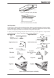
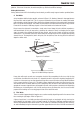
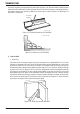


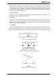


Table Of Contents
- 0-5143-CCr
- SECTION 1: ARC WELDING SAFETY INSTRUCTIONS AND WARNINGS
- SECTION 2: INTRODUCTION
- SECTION 3: INSTALLATION, OPERATION AND SETUP
- 3.01 Environment
- 3.02 Location
- 3.03 Ventilation
- 3.04 Mains Supply Voltage Requirements
- 3.05 Electromagnetic Compatibility
- 3.06 Transtig 170Pi Power Source Controls, Indicators and Features
- 3.07 Shielding Gas Regulator Operating Instructions
- 3.08 Setup for TIG (GTAW) Welding
- 3.09 Foot Control Part No. W4015800 (Optional Accessory)
- 3.10 Setup for Manual Arc (MMAW) Welding
- SECTION 4: BASIC WELDING GUIDE
- SECTION 5: POWER SOURCE PROBLEMS AND ROUTINE SERVICE REQUIREMENTS
- SECTION 6: KEY SPARE PARTS
- APPENDIX: TRANSTIG 170Pi CIRCUIT DIAGRAM
- CIGWELD - LIMITED WARRANTY TERMS
- TERMS OF WARRANTY – January 2013
- WARRANTY SCHEDULE – January 2013
- GLOBAL CUSTOMER SERVICE CONTACT INFORMATION
- SECTION 1: ARC WELDING SAFETY INSTRUCTIONS AND WARNINGS
- SECTION 2: INTRODUCTION
- SECTION 3: INSTALLATION, OPERATION AND SETUP
- 3.01 Environment
- 3.02 Location
- 3.03 Ventilation
- 3.04 Mains Supply Voltage Requirements
- 3.05 Electromagnetic Compatibility
- 3.06 Transmig 175i Power Source Controls, Indicators and Features
- 3.14 Shielding Gas Regulator Operating Instructions
- 3.17 Setup for TIG (GTAW) Welding
- 3.18 Setup for Manual Arc (MMAW) Welding
- SECTION 4: BASIC WELDING GUIDE
- SECTION 5: POWER SOURCE PROBLEMS AND ROUTINE SERVICE REQUIREMENTS
- AP0-5143-APENDIX
- CIGWELD - LIMITED WARRANTY TERMS
- TERMS OF WARRANTY - JULY 2010
- WARRANTY SCHEDULE - JULY 2010
- GLOBAL CUSTOMER SERVICE CONTACT INFORMATION
TRANSTIG 170Pi
Manual 0-5241 4-3 BASIC WELDING GUIDE
Art# A-07693
Figure 4-7: Overhead Position, Butt Weld
Art # A-07694
Figure 4-8: Overhead Position, Fillet Weld
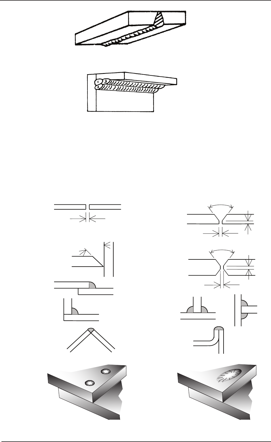
Joint Preparations
In many cases, it will be possible to weld steel sections without any special preparation. For heavier sections
and for repair work on castings, etc., it will be necessary to cut or grind an angle between the pieces being
joined to ensure proper penetration of the weld metal and to produce sound joints.
In general, surfaces being welded should be clean and free of rust, scale, dirt, grease, etc. Slag should be
removed from oxy-cut surfaces. Typical joint designs are shown in Figure 4-9.
Gap varies from
1.6mm (1/16”) to 4.8mm (3/16”)
depending on plate thickness
Joint
Open Square Butt
1.6mm (1/16” ) max
1.6mm (1/16”)
Single Vee Butt Joint
Not less than
70°
Double Vee Butt Joint
1.6mm (1/16”)
Lap Joint
Tee Joints
(Fillet both sides of the
joint)
Edge Joint
Fillet Joint
Corner Weld
Plug Weld Plug Weld
Not less than
70°
Single Vee Butt Joint
Not less than
45°
1.6mm (1/16”) max
Art # A-07695_AE
Figure 4-9: Typical Joint Designs for Arc Welding