
User guide


Table Of Contents
- 0-5143-CCr
- SECTION 1: ARC WELDING SAFETY INSTRUCTIONS AND WARNINGS
- SECTION 2: INTRODUCTION
- SECTION 3: INSTALLATION, OPERATION AND SETUP
- 3.01 Environment
- 3.02 Location
- 3.03 Ventilation
- 3.04 Mains Supply Voltage Requirements
- 3.05 Electromagnetic Compatibility
- 3.06 Transtig 170Pi Power Source Controls, Indicators and Features
- 3.07 Shielding Gas Regulator Operating Instructions
- 3.08 Setup for TIG (GTAW) Welding
- 3.09 Foot Control Part No. W4015800 (Optional Accessory)
- 3.10 Setup for Manual Arc (MMAW) Welding
- SECTION 4: BASIC WELDING GUIDE
- SECTION 5: POWER SOURCE PROBLEMS AND ROUTINE SERVICE REQUIREMENTS
- SECTION 6: KEY SPARE PARTS
- APPENDIX: TRANSTIG 170Pi CIRCUIT DIAGRAM
- CIGWELD - LIMITED WARRANTY TERMS
- TERMS OF WARRANTY – January 2013
- WARRANTY SCHEDULE – January 2013
- GLOBAL CUSTOMER SERVICE CONTACT INFORMATION
- SECTION 1: ARC WELDING SAFETY INSTRUCTIONS AND WARNINGS
- SECTION 2: INTRODUCTION
- SECTION 3: INSTALLATION, OPERATION AND SETUP
- 3.01 Environment
- 3.02 Location
- 3.03 Ventilation
- 3.04 Mains Supply Voltage Requirements
- 3.05 Electromagnetic Compatibility
- 3.06 Transmig 175i Power Source Controls, Indicators and Features
- 3.14 Shielding Gas Regulator Operating Instructions
- 3.17 Setup for TIG (GTAW) Welding
- 3.18 Setup for Manual Arc (MMAW) Welding
- SECTION 4: BASIC WELDING GUIDE
- SECTION 5: POWER SOURCE PROBLEMS AND ROUTINE SERVICE REQUIREMENTS
- AP0-5143-APENDIX
- CIGWELD - LIMITED WARRANTY TERMS
- TERMS OF WARRANTY - JULY 2010
- WARRANTY SCHEDULE - JULY 2010
- GLOBAL CUSTOMER SERVICE CONTACT INFORMATION
TRANSTIG 170Pi
Manual 0-5241 3-13 INSTALLATION, OPERATION AND SETUP
Note that when the unit is powered on the mode selection control will automatically default to LIFT TIG/HF
TIG mode. This is necessary so as to prevent inadvertent arcing should an electrode holder be connected
to the unit and mistakenly be in contact with the work piece during power up.
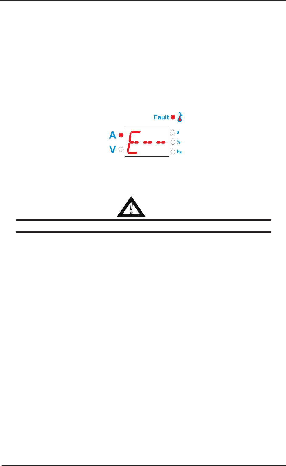
11. Thermal Overload Indicator
This welding power source is protected by a self resetting thermostat. The indicator will illuminate if the
duty cycle of the power source has been exceeded. Should the thermal overload indicator illuminate the
output of the power source will be disabled. Once the power source cools down this light will go OFF and
the over temperature condition will automatically reset. Note that the mains power switch should remain
in the on position such that the fan continues to operate thus allowing the unit to cool sufficiently. Do not
switch the unit off should a thermal overload condition be present.
The display will also show error code E-- in the event of an over current or over temperature.
A-11665
12. Shielding Gas Inlet
The Shielding Gas Inlet connection is used to supply the appropriate shielding gas to the unit. Refer to
section 3.08 for GTAW (TIG) set up details.
!
WARNING
Only Inert Shielding Gases specifically designed for welding applications should be used.
13. On / Off Switch
This switch is used to turn the unit on/off.
14. Fan on Demand
The Transtig 170Pi is fitted with a fan on demand feature. Fan on demand automatically switches the cooling
fan off when it is not required. This has two main advantages; (1) to minimize power consumption, and
(2) to minimize the amount of contaminants such as dust that are drawn into the power source.
Note that the fan will only operate when required for cooling purposes and will automatically switch off
when not required.