
User guide
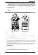
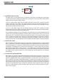
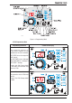

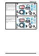
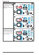
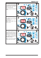
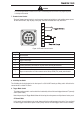
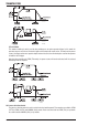
Table Of Contents
- 0-5143-CCr
- SECTION 1: ARC WELDING SAFETY INSTRUCTIONS AND WARNINGS
- SECTION 2: INTRODUCTION
- SECTION 3: INSTALLATION, OPERATION AND SETUP
- 3.01 Environment
- 3.02 Location
- 3.03 Ventilation
- 3.04 Mains Supply Voltage Requirements
- 3.05 Electromagnetic Compatibility
- 3.06 Transtig 170Pi Power Source Controls, Indicators and Features
- 3.07 Shielding Gas Regulator Operating Instructions
- 3.08 Setup for TIG (GTAW) Welding
- 3.09 Foot Control Part No. W4015800 (Optional Accessory)
- 3.10 Setup for Manual Arc (MMAW) Welding
- SECTION 4: BASIC WELDING GUIDE
- SECTION 5: POWER SOURCE PROBLEMS AND ROUTINE SERVICE REQUIREMENTS
- SECTION 6: KEY SPARE PARTS
- APPENDIX: TRANSTIG 170Pi CIRCUIT DIAGRAM
- CIGWELD - LIMITED WARRANTY TERMS
- TERMS OF WARRANTY – January 2013
- WARRANTY SCHEDULE – January 2013
- GLOBAL CUSTOMER SERVICE CONTACT INFORMATION
- SECTION 1: ARC WELDING SAFETY INSTRUCTIONS AND WARNINGS
- SECTION 2: INTRODUCTION
- SECTION 3: INSTALLATION, OPERATION AND SETUP
- 3.01 Environment
- 3.02 Location
- 3.03 Ventilation
- 3.04 Mains Supply Voltage Requirements
- 3.05 Electromagnetic Compatibility
- 3.06 Transmig 175i Power Source Controls, Indicators and Features
- 3.14 Shielding Gas Regulator Operating Instructions
- 3.17 Setup for TIG (GTAW) Welding
- 3.18 Setup for Manual Arc (MMAW) Welding
- SECTION 4: BASIC WELDING GUIDE
- SECTION 5: POWER SOURCE PROBLEMS AND ROUTINE SERVICE REQUIREMENTS
- AP0-5143-APENDIX
- CIGWELD - LIMITED WARRANTY TERMS
- TERMS OF WARRANTY - JULY 2010
- WARRANTY SCHEDULE - JULY 2010
- GLOBAL CUSTOMER SERVICE CONTACT INFORMATION
TRANSTIG 170Pi
INSTALLATION, OPERATION AND SETUP 3-10 Manual 0-5241
Crater Current
This parameter operates in TIG
modes only.
In 2T mode this is the current at
the end of the down slope current
ramp. When the welding current
reaches the Crater Current value,
the welding current will cease and
the unit will enter Post Flow mode.
In 4T mode, this is the current at
the end of the down slope current
ramp. The welding current will
remain at the Crater Current value
until the torch trigger is released, at
which time the welding current will
cease and the unit will enter Post
Flow mode.
Range is 5 to 170A. Factory default
is 30A.
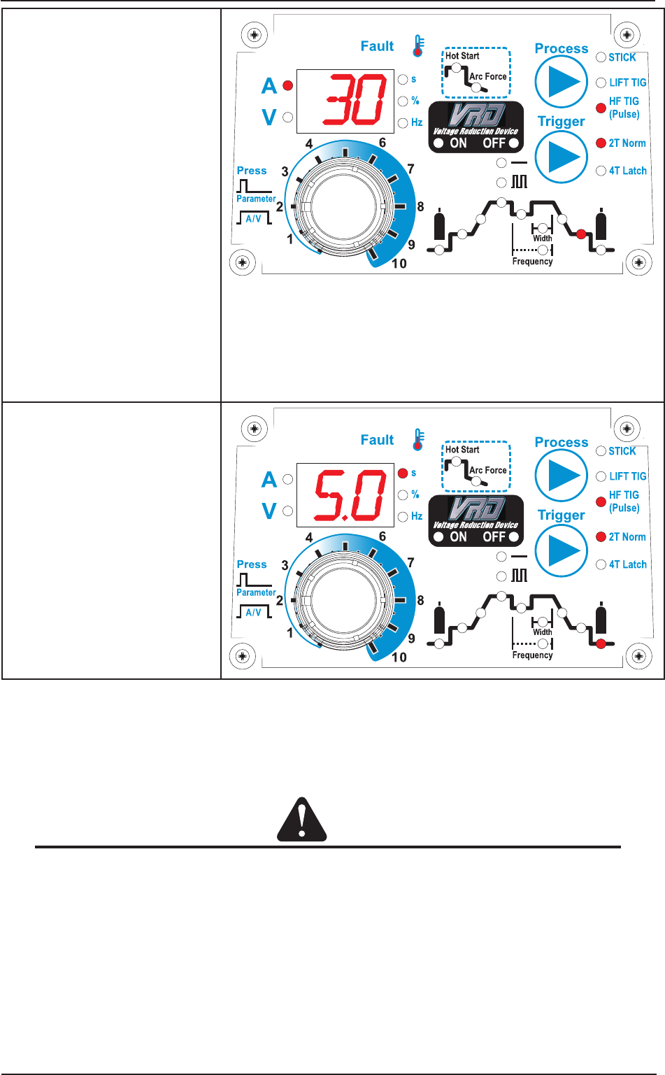
Post Flow
This parameter operates in TIG
modes only and is used to adjust
the post gas flow time once the
arc has extinguished. This control
is used to dramatically reduce
oxidation of the tungsten electrode.
Range is 0.0 to 30.0 seconds.
Factory default is 5.0 seconds.
5. Positive Welding Output Terminal
The positive welding terminal is used to connect the welding output of the power source to the electrode
holder lead or work lead. Positive welding current flows from the power source via this heavy duty bayonet
type terminal. It is essential, however, that the male plug is inserted and turned securely to achieve a
sound electrical connection.
CAUTION
Loose welding terminal connections can cause overheating and result in the male plug being fused
in the bayonet terminal.
6. Negative Welding Output Terminal
The negative welding terminal is used to connect the welding output of the power source to the TIG
torch or work lead. Negative welding current flows to the power source via this heavy duty bayonet type
terminal. It is essential, however, that the male plug is inserted and turned securely to achieve a sound
electrical connection.