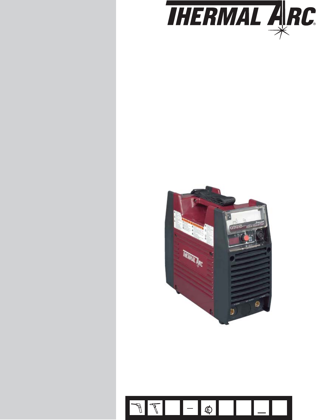
60 S ® ARCMASTER INVERTER ARC WELDER Operating Manual Version No: 1 Issue Date: March 31, 2006 Manual No: 0-4854 Operating Features: 1 SMAW GTAW PHASE 50 Hz 60 INVERTER 115 V 230 V CC DC
WE APPRECIATE YOUR BUSINESS! Congratulations on your new Thermal Arc® product. We are proud to have you as our customer and will strive to provide you with the best service and reliability in the industry. This product is backed by our extensive warranty and world-wide service network. To locate your nearest distributor or service agency call 800-752-7621, or visit us on the web at www.thermalarc.com.
! WARNING Read and understand this entire Manual and your employer’s safety practices before installing, operating, or servicing the equipment. While the information contained in this Manual represents the Manufacturer’s best judgment, the Manufacturer assumes no liability for its use. Instruction Manual Number 0-4854 for: ArcMaster 160 S Inverter Welding Power Supply Part No. 10-3066 Published by: Thermadyne Industries, Inc. 82 Benning Street West Lebanon, New Hampshire, USA 03784 (603) 298-5711 www.
ARCMASTER® 160 S Table of Contents SECTION 1: SAFETY INSTRUCTIONS AND WARNINGS .................................................. 1-1 1.01 Arc Welding Hazards.................................................................................1-1 1.02 Principal Safety Standards ........................................................................1-4 1.03 Precautions de Securite en Soudage A L’Arc ............................................1-5 1.04 Dangers relatifs au soudage à l’arc ........................
ARCMASTER® 160 S SECTION 7: BASIC TIG WELDING GUIDE ................................................................... 7-1 7.01 Electrode Polarity ......................................................................................7-1 7.02 Tungsten Electrode Current Ranges ..........................................................7-1 7.03 Tungsten Electrode Types .........................................................................7-1 7.04 Guide for Selecting Filler Wire Diameter ....................
ARCMASTER® 160 S iv March 31, 2006
ARCMASTER® 160 S SECTION 1: SAFETY INSTRUCTIONS AND WARNINGS ! WARNING PROTECT YOURSELF AND OTHERS FROM POSSIBLE SERIOUS INJURY OR DEATH. KEEP CHILDREN AWAY. PACEMAKER WEARERS KEEP AWAY UNTIL CONSULTING YOUR DOCTOR. DO NOT LOSE THESE INSTRUCTIONS. READ OPERATING/INSTRUCTION MANUAL BEFORE INSTALLING, OPERATING OR SERVICING THIS EQUIPMENT.
ARCMASTER® 160 S 1. Protect yourself and others from flying sparks and hot metal. 2. Do not weld where flying sparks can strike flammable material. WARNING FUMES AND GASES can be hazardous to your health. Welding produces fumes and gases. Breathing these fumes and gases can be hazardous to your health. 3. Remove all flammables within 35 ft (10.7 m) of the welding arc. If this is not possible, tightly cover them with approved covers. 4.
ARCMASTER® 160 S 3. Allow engine to cool before fueling. If possible, check and add fuel to cold engine before beginning job. WARNING 4. Do not overfill tank — allow room for fuel to expand. 5. Do not spill fuel. If fuel is spilled, clean up before starting engine. CYLINDERS can explode if damaged. Shielding gas cylinders contain gas under high pressure. If damaged, a cylinder can explode. Since gas cylinders are normally part of the welding process, be sure to treat them carefully.
ARCMASTER® 160 S ! 1.02 Principal Safety Standards WARNING This product, when used for welding or cutting, produces fumes or gases which contain chemicals know to the State of California to cause birth defects and, in some cases, cancer. (California Health & Safety code Sec. 25249.5 et seq.) NOTE Considerations About Welding And The Effects of Low Frequency Electric and Magnetic Fields The following is a quotation from the General Conclusions Section of the U.S.
ARCMASTER® 160 S 1.03 Precautions De Securite En Soudage A L’arc ! MISE EN GARDE LE SOUDAGE A L’ARC EST DANGEREUX PROTEGEZ-VOUS, AINSI QUE LES AUTRES, CONTRE LES BLESSURES GRAVES POSSIBLES OU LA MORT. NE LAISSEZ PAS LES ENFANTS S’APPROCHER, NI LES PORTEURS DE STIMULATEUR CARDIAQUE (A MOINS QU’ILS N’AIENT CONSULTE UN MEDECIN). CONSERVEZ CES INSTRUCTIONS. LISEZ LE MANUEL D’OPERATION OU LES INSTRUCTIONS AVANT D’INSTALLER, UTILISER OU ENTRETENIR CET EQUIPEMENT.
ARCMASTER® 160 S 4. Portez des vêtements en matériaux ignifuges et durables (laine et cuir) et des chaussures de sécurité. 5. Portez un casque antibruit ou des bouchons d’oreille approuvés lorsque le niveau de bruit est élevé. 7. Ne soudez des tôles galvanisées ou plaquées au plomb ou au cadmium que si les zones à souder ont été grattées à fond, que si l’espace est bien ventilé; si nécessaire portez un respirateur à adduction d’air.
ARCMASTER® 160 S 6. N’oubliez pas qu’une soudure réalisée sur un plafond, un plancher, une cloison ou une paroi peut enflammer l’autre côté. 7. Ne soudez pas un récipient fermé, tel un réservoir ou un baril. 8. Connectez le câble de soudage le plus près possible de la zone de soudage pour empêcher le courant de suivre un long parcours inconnu, et prévenir ainsi les risques d’électrocution et d’incendie. 9. Ne dégelez pas les tuyaux avec un source de courant. 10.
ARCMASTER® 160 S 6. Réinstallez les capots ou les protecteurs et fermez les portes après des travaux d’entretien et avant de faire démarrer le moteur. 1.05 Principales Normes De Securite Safety in Welding and Cutting, norme ANSI Z49.1, American Welding Society, 550 N.W. LeJeune Rd., Miami, FL 33128. Safety and Health Standards, OSHA 29 CFR 1910, Superintendent of Documents, U.S. Government Printing Office, Washington, D.C. 20402.
ARCMASTER® 160 S SECTION 2: INTRODUCTION AND DESCRIPTION 2.01 How To Use This Manual 2.02 Equipment Identification This Owner’s Manual applies to just specification or part numbers listed on page i. To ensure safe operation, read the entire manual, including the chapter on safety instructions and warnings. Throughout this manual, the words WARNING, CAUTION, and NOTE may appear. Pay particular attention to the information provided under these headings.
ARCMASTER® 160 S 2.04 Symbol Chart Note that only some of these symbols will appear on your model. On Single Phase Wire Feed Function Off Three Phase Wire Feed Towards Workpiece With Output Voltage Off.
ARCMASTER® 160 S 2.05 Description The Thermal Arc™ ArcMaster 160 S is a self contained single-phase DC arc welding power sources with Constant Current (CC) output characteristics. This unit is equipped with a Digital Volt/Amperage Meter and lift arc starter, and high-frequency arc starter for use with Gas Tungsten Arc Welding (GTAW), and Shielded Metal Arc Welding (SMAW) processes. The power source is totally enclosed in an impact resistant, flame resistant and non-conductive plastic case.
ARCMASTER® 160 S 2.07 Transporting Methods These units are equipped with a handle for carrying purposes. ! WARNING ELECTRIC SHOCK can kill. DO NOT TOUCH live electrical parts. Disconnect input power conductors from de-energized supply line before moving the welding power source. ! WARNING FALLING EQUIPMENT can cause serious personal injury and equipment damage. Lift unit with handle on top of case. Use handcart or similar device of adequate capacity.
ARCMASTER® 160 S SECTION 3: INSTALLATION RECOMMENDATIONS 3.03 Electrical Input Connections 3.01 Environment The ArcMaster 160 S is designed for use in adverse environments. Examples of environments with increased adverse conditions are a. In locations in which freedom of movement is restricted, so that the operator is forced to perform the work in a cramped (kneeling, sitting or lying) position with physical contact with conductive parts, b.
ARCMASTER® 160 S Refer to figure 3 and: 1. Connect end of ground (GREEN) conductor to a suitable ground. Use a grounding method that complies with all applicable electrical codes. 2. Connect ends of line 1 (BLACK) and line 2 (WHITE) input conductors to a de-energized line disconnect switch. 3. Use Table 1 and Table 2 as a guide to select line fuses for the disconnect switch.
ARCMASTER® 160 S 3.04 Specifications Parameter Rated Output Amperes Volts Duty Cycle Duty Cycle TIG STICK Output Current TIG Range STICK Open Circuit Voltage Dimensions Width Height Length Weight 160 S 115VAC 230VAC 85 160 23 27 100% 35% 160A / 17V @ 35% 230VAC 130A / 15V @ 60% 230VAC 100A / 14V @ 100% 230VAC 85A / 13V @ 100% 115VAC 160A / 27V @ 35% 230VAC 130A / 25V @ 60% 230VAC 100A / 24V @ 100% 230VAC 85A / 23V @ 100% 115VAC 5 – 160 (230V), 5 – 85 (115V) 5 – 160 (230V), 5 – 85 (115V) 65V 5.
ARCMASTER® 160 S 3.05 Duty Cycle The duty cycle of a welding power source is the percentage of a ten (10) minute period that it can be operated at a given output without causing overheating and damage to the unit. If the welding amperes decrease, the duty cycle increases. If the welding amperes are increased beyond the rated output, the duty cycle will decrease.
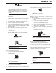
SECTION 4: OPERATOR CONTROLS ARCMASTER® 160 S 4.01 ArcMaster 160 S Controls Figure 4 – ArcMaster 160 S Power Source the digital meter. Pushing the knob inward displays the actual welding voltage. 2. Remote Control Socket 1. Control Knob This control sets the selected weld parameter, rotating it clockwise increases the parameter and is indicated on Gnd. 2 12345678 1 5 4 3 8 7 6 The 8 pin Remote Control Socket is used to connect remote current control devices to the welding Power Source.
ARCMASTER® 160 S 3. Positive Terminal 5. ON/OFF Switch Welding current flows from the Power Source via heavy duty Dinse type terminal. It is essential, however, that the male plug is inserted and turned securely to achieve a sound electrical connection. This switch connects the Primary supply voltage to the inverter when in the ON position. This enables the Power Supply. ! 4. Negative Terminal Welding current flows from the Power Source via heavy duty Dinse type terminal.
ARCMASTER® 160 S 4.03 Weld Parameters for ArcMaster 160 S Weld Mode Weld Parameter HOT START Parameter Range 0 to 70A WELD CUR ARC CONTROL 5 to 85A 115V 5 to 160A 230V Factory Setting 20A Incremental Unit 1A STICK Yes LIFT TIG No 80A 1A Yes Yes Yes No 0 to 100% 10% 1% Table 4 – Weld Parameters for ArcMaster 160 S 4.
ARCMASTER® 160 S 4-4 March 31, 2006
ARCMASTER® 160 S SECTION 5: SET-UP FOR SMAW (STICK) AND GTAW (TIG) Conventional operating procedures apply when using the Welding Power Source, i.e. connect work lead directly to work piece and electrode lead is used to hold electrode. Wide safety margins provided by the coil design ensure that the Welding Power Source will withstand short-term overload without adverse effects. The welding current range values should be used as a guide only.
ARCMASTER® 160 S 5-2 March 31, 2006
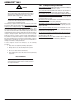
SECTION 6: SEQUENCE OF OPERATION ARCMASTER® 160 S NOTE: Scroll Buttons are used to select the parameters to be set. The LED’s show which function is being adjusted on the weld sequence graph. Refer to Symbols Table located in the front of the manual for Symbol descriptions. 5 1 2 3 Figure 7-1: 160 S Front Panel 4 1. Scroll Buttons– used to select the parameter to be set. 3.
ARCMASTER® 160 S 6-2 March 31, 2006
ARCMASTER® 160 S SECTION 7: BASIC TIG WELDING GUIDE 7.01 Electrode Polarity Connect the TIG torch to the - / TORCH terminal and the work lead to the + / WORK terminal for direct current straight polarity. Direct current straight polarity is the most widely used polarity for DC TIG welding. It allows limited wear of the electrode since 70% of the heat is concentrated at the work piece. 7.02 Tungsten Electrode Current Ranges Electrode Diameter DC Current (Amps) 0.040” (1.0mm) 30 – 60 1/16” (1.
ARCMASTER® 160 S 7.05 Shielding Gas Selection Alloy Shielding Gas Aluminium & alloys Welding Argon Carbon Steel Welding Argon Stainless Steel Welding Argon Nickel Alloy Welding Argon Copper Welding Argon Titanium Welding Argon Table 7 – Shielding gas selection 7.06 TIG Welding Parameters for Low Carbon & Low Alloy Steel Pipe Electrode Type & Diameter Thoriated 2% 3/32” (2.4 mm) Current Range DC Amperes 120 - 170 Filler Rod for Root Pass Yes Thoriated 2% 3/32” (2.
ARCMASTER® 160 S SECTION 8: BASIC ARC WELDING GUIDE 8.01 Electrode Polarity Cast Iron Stick electrodes are generally connected to the ‘+’ terminal and the work lead to the ‘−’ terminal but if in doubt consult the electrode manufacturers literature. 8.02 Effects of Stick Welding Various Materials Most types of cast iron, except white iron, are weldable. White iron, because of its extreme brittleness, generally cracks when attempts are made to weld it.
ARCMASTER® 160 S 8-2 March 31, 2006
ARCMASTER® 160 S SECTION 9: ROUTINE MAINTENANCE The only routine maintenance required for the power supply is a thorough cleaning and inspection, with the frequency depending on the usage and the operating environment. ! WARNING Disconnect primary power at the source before opening the enclosure. Wait at least two minutes before opening the enclosure to allow the primary capacitors to discharge.
ARCMASTER® 160 S Warning! Disconnect input power before maintaining. Maintain more often if used under severe conditions Each Use Visual check of torch Consumable parts Visual check of regulator and pressure Weekly Visually inspect the torch body and consumables Visually inspect the cables and leads.
ARCMASTER® 160 S SECTION 10: BASIC TROUBLESHOOTING ! WARNING There are extremely dangerous voltages and power levels present inside this product. Do not attempt to open or repair unless you are an Accredited Thermal Arc Service Agent and you have had training in power measurements and troubleshooting techniques. If major complex subassemblies are faulty, then the Welding Power Source must be returned to an Accredited Thermal Arc Service Agent for repair.
ARCMASTER® 160 S 8. Description Electrode melts or oxidizes when an arc is struck. Possible Cause A. No gas flowing to welding region. B. Torch is clogged with dust. C. Gas hose is cut. D. Gas passage contains impurities. 9. Poor weld finish. E. Gas regulator turned off. F. Torch valve is turned off. G. The electrode is too small for the welding current. Inadequate shielding gas. Remedy A. Check the gas lines for kinks or breaks and gas cylinder contents. B. Clean torch C. Replace gas hose. D.
ARCMASTER® 160 S 10.02 Stick Welding Problems Description 1. Gas pockets or voids in weld metal (Porosity). 2. Crack occurring in weld metal soon after solidification commences A. B. C. A. Possible Cause Electrodes are damp. Welding current is too high. Surface impurities such as oil, grease, paint, etc. Rigidity of joint. B. Insufficient throat thickness. 3. A gap is left by failure of the weld metal to fill the root of the weld. C. Cooling rate is too high. A. Welding current is too low. B.
ARCMASTER® 160 S 5. Non-metallic parti cles are A. Non-metallic particles may be trapped A. If bad undercut is present, clean slag trapped in the weld metal in undercut from previous run. out and cover with a run from a smaller (slag inclusion). diameter electrode. B. Joint preparation too restricted. B. Allow for adequate penetration and room for cleaning out the slag. C. Irregular deposits allow slag to be C. I f v e r y b a d , c h i p o r g r i n d o u t trapped. irregularities. D.
ARCMASTER® 160 S SECTION 11: VOLTAGE REDUCTION DEVICE (VRD) 11.01 VRD Specification Description VRD Open Circuit Voltage ArcMaster 160 S 15.3 to 19.8V VRD Resistance 148 to 193 ohms VRD Turn OFF Time 0.2 to 0.3 seconds Notes Open circuit voltage between welding terminals The required resistance between welding terminals to turn ON the welding power The time taken to turn OFF the welding power once the welding current has stopped 11.
ARCMASTER® 160 S 11.03 Switching VRD On/Off Switch the machine Off. a) Remove the clear plastic cover from the control panel (see Figure 11). • Lift up the cover so it rests on the top of the unit. • Place a small flat bladed screw driver between the cover hinge on the front panel. • Gently lift the cover hinge out of the front cover mounting hole. • Remove the control’s clear plastic cover. b) Remove four mounting screws from the control panel (see Figure 12).
ARCMASTER® 160 S 1 1 2 1 1 Figure 11-2: VRD ON/OFF Step B,C ! WARNING The VRD ON/OFF trim potentiometer MUST ONLY be positioned fully clockwise OR fully counter clockwise as the VRD function will be unknown for every other position.
ARCMASTER® 160 S 11-4 March 31, 2006
March 31, 2006 6. E99 error code displayed Mains supply (input) voltage has been turned off but control circuit has power from the primary capacitors. Table 12-1: Power Source Error Codes A. Main on/off switch on machine has A. Turn on/off switch on. been turned off. B. Mains supply (input) voltage has B. Have an accredited Thermal Arc been turned off. Agent or a qualified electrician check the Mains voltage and fuses. Possible Cause Remedy A. The Welding Power Source’s duty A .
ARCMASTER® 160 S 12-2 March 31, 2006
ARCMASTER® 160 S SECTION 13: OPTIONS AND ACCESSORIES PRODUCT Carry Case PART NO. DESCRIPTION 600304 Accommodates the power supply, regulator, stick work lead, TIG torch & accessory kit Stick Kit 90924A Work clamp with 15’ #4 cable, and stick electrode with 15’ #4 cable TIG Kit 600288 Includes regulator/flowgauge, 12.
ARCMASTER® 160 S PCB2 Main Circuit Board [WK-5467] Q1A TB7 C C G E G E C Q1B Q3A Q3B C D1 G E + TB1 S1 Line1 TB10 TB11 TB2 TB9 C PCB6 IGBTGate TB2 Circuit Board [WK-5460] TB8 Line2 + TB12 Q1C Q2A FAN1 + Q2B 1 2 3 4 CN2 1 2 Q4B C TB5 TB6 C CN1 CN5 - Q4A G E G E TB6 TB7 C G E C SIDE CHASSIS 1 G E TB3 - TB5 Q3CTB4 C PCB7 IGBTGate Circuit Board [WK-5460] G E C TB3 + Ground TB1 G E G E G E Q2C Q4C C CN1 1 2 3 4 5 6 1 2 3 4 5 6 1 2 3 4 5 6 1 2 3 4
ARCMASTER® 160 S PCB3 2nd Diode Circuit Board [WK-5468] D2 T1 CT1 TO1 TB1 12 34 TB3 +Output Terminal TB5 TB7 D3 TB2 +12 -12 IS GND TB4 TB6 SIDE CHASSIS 2 C1 FCH1 R1 TO2 -Output Terminal CN1 1 2 3 4 5 6 1 2 3 4 5 6 7 CN1 +12 -12 IS GND PCB4 Control Circuit Board [WK-5449] CN2 CN2 CN3 PCB5 Panel Circuit Board [WK-5448] March 31, 2006 A-3
LIMITED WARRANTY This information applies to Thermal Arc products that were purchased in the USA and Canada. April 2006 LIMITED WARRANTY: Thermal Arc®, Inc., A Thermadyne Company ("Thermal Arc"), warrants to customers of authorized distributors ("Purchaser") that its products will be free of defects in workmanship or material.
WARRANTY SCHEDULE This information applies to Thermal Arc products that were purchased in the USA and Canada. April 2006 ENGINE DRIVEN WELDERS W ARRANTY P ERIOD Scout, Raider, Explorer Original Main Power Stators and Inductors .................................................................................. 3 years LABOR 3 years Original Main Power Rectifiers, Control P.C. Boards ...................................................................
GLOBAL CUSTOMER SERVICE CONTACT INFORMATION Thermadyne USA Thermadyne Asia Sdn Bhd 2800 Airport Road Denton, Tx 76207 USA Telephone: (940) 566-2000 800-426-1888 Fax: 800-535-0557 Email: sales@thermalarc.
World Headquarters Thermadyne Holdings Corporation Suite 300, 16052 Swingley Ridge Road St. Louis, MO 63017 Telephone: (636) 728-3000 Fascimile: (636) 728-3010 Email: sales@thermalarc.com www.thermalarc.