51 CUTMASTER ™ AUTOMATED PLASMA CUTTING SYSTEM SL100SV PLASMA CUTTING MACHINE TORCH Art # A-04611 Operating Manual Rev. AF.
WE APPRECIATE YOUR BUSINESS! Congratulations on your new Thermal Dynamics product. We are proud to have you as our customer and will strive to provide you with the best service and reliability in the industry. This product is backed by our extensive warranty and world-wide service network. To locate your nearest distributor or service agency call 1-800426-1888, or visit us on the web at www.thermal-dynamics.com.
WARNINGS Read and understand this entire Manual and your employer’s safety practices before installing, operating, or servicing the equipment. While the information contained in this Manual represents the Manufacturer's best judgement, the Manufacturer assumes no liability for its use. Automated Plasma Cutting System Automated CutMaster™ 151 Power Supply SL100 Machine Torch Operating Manual Number 0-4691 Covered under U.S. Patents.
TABLE OF CONTENTS SECTION 1: GENERAL INFORMATION ................................................................................................ 1-1 1.01 1.02 1.03 1.04 1.05 1.06 1.07 1.08 Notes, Cautions and Warnings ...................................................................... Important Safety Precautions ....................................................................... Publications ..................................................................................................
TABLE OF CONTENTS (continued) SECTION 5: SERVICE .......................................................................................................................... 5-1 5.01 5.02 5.03 5.04 5.05 5.06 5.07 5.10 5.11 5.12 General Maintenance .................................................................................... 5-1 Common Faults ............................................................................................ 5-5 Basic Troubleshooting ...........................................
TABLE OF CONTENTS (continued) APPENDIX 10: INTERFACE PCB SWITCH SETTINGS (Division Factors 30-33) .............................................. A-10 APPENDIX 11: INTERFACE PCB SWITCH SETTINGS (Division Factors 33-36) .............................................. A-11 APPENDIX 12: INTERFACE PCB SWITCH SETTINGS (Division Factors 36-43) .............................................. A-12 APPENDIX 13: INTERFACE PCB SWITCH SETTINGS (Division Factors 43-50) ..............................................
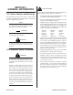
SECTION 1: GENERAL INFORMATION GASES AND FUMES Gases and fumes produced during the plasma cutting process can be dangerous and hazardous to your health. 1.01 Notes, Cautions and Warnings • Keep all fumes and gases from the breathing area. Keep your head out of the welding fume plume. Throughout this manual, notes, cautions, and warnings are used to highlight important information.
NOISE ELECTRIC SHOCK Electric Shock can injure or kill. The plasma arc process uses and produces high voltage electrical energy. This electric energy can cause severe or fatal shock to the operator or others in the workplace. Noise can cause permanent hearing loss. Plasma arc processes can cause noise levels to exceed safe limits. You must protect your ears from loud noise to prevent permanent loss of hearing. • Never touch any parts that are electrically “live” or “hot.
1.03 Publications Refer to the following standards or their latest revisions for more information: 1. OSHA, SAFETY AND HEALTH STANDARDS, 29CFR 1910, obtainable from the Superintendent of Documents, U.S. Government Printing Office, Washington, D.C. 20402 2. ANSI Standard Z49.1, SAFETY IN WELDING AND CUTTING, obtainable from the American Welding Society, 550 N.W. LeJeune Rd, Miami, FL 33126 3.
1.05 Precautions De Securite Importantes AVERTISSEMENTS L’OPÉRATION ET LA MAINTENANCE DU MATÉRIEL DE SOUDAGE À L’ARC AU JET DE PLASMA PEUVENT PRÉSENTER DES RISQUES ET DES DANGERS DE SANTÉ. Coupant à l’arc au jet de plasma produit de l’énergie électrique haute tension et des émissions magnétique qui peuvent interférer la fonction propre d’un “pacemaker” cardiaque, les appareils auditif, ou autre matériel de santé electronique.
INCENDIE ET EXPLOSION • Utilisez la nuance de lentille qui est suggèrée dans le recommendation qui suivent ANSI/ASC Z49.1: Courant Arc Les incendies et les explosions peuvent résulter des scories chaudes, des étincelles ou de l’arc de plasma. Le procédé à l’arc de plasma produit du métal, des étincelles, des scories chaudes pouvant mettre le feu aux matières combustibles ou provoquer l’explosion de fumées inflammables. • Procurez une bonne aération de toutes les fumées inflammables ou explosives.
4. Norme ANSI Z87.1, PRATIQUES SURES POUR LAPROTECTION DES YEUX ET DU VISAGE AU TRAVAIL ET DANS LES ECOLES, disponible de l’Institut Américain des Normes Nationales (American National Standards Institute), 1430 Broadway, New York, NY 10018 5. NormeANSI Z41.1, NORMES POUR LES CHAUSSURES PROTECTRICES, disponible auprès de l’American National Standards Institute, 1430 Broadway, New York, NY 10018 14. Norme AWSF4.
1.07 Declaration of Conformity Manufacturer: Address: Thermal Dynamics Corporation 82 Benning Street West Lebanon, New Hampshire 03784 USA The equipment described in this manual conforms to all applicable aspects and regulations of the ‘Low Voltage Directive’ (European Council Directive 73/23/EEC as amended by Council Directive 93/68/EEC) and to the National legislation for the enforcement of this Directive.
1.08 Statement of Warranty LIMITED WARRANTY: Subject to the terms and conditions established below, Thermal Dynamics® Corporation warrants to the original retail purchaser that new Thermal Dynamics CUTMASTER™ 1Series plasma cutting systems sold after the effective date of this warranty are free of defects in material and workmanship.
SECTION 2: SPECIFICATIONS 2.01 Scope of Manual This manual contains descriptions, operating instructions and basic maintenance procedures for the Thermal Dynamics Automated CutMaster 151 Plasma Cutting System. Servicing of this equipment is restricted to properly trained personnel; unqualified personnel are strictly cautioned against attempting repairs or adjustments not covered in this manual, at the risk of voiding the Warranty. Read this manual thoroughly.
Power Supply Dimensions & Weight Ventilation Clearance Requirements Art # A-03379 83 lb / 37.6 kg 6" 150 mm 17.3 in / 439 mm 24" 0.6 m 27.5 in / 696 mm 2 6" 150 mm 12.4 in / 315 mm A-03572 6" 150 mm 2.03 Input Wiring Specifications Input Voltage Freq.
2.
2.05 Power Supply Options and Accessories Section 6, Parts Lists, provides catalog numbers and ordering information. A. Single-Stage Air Filter Kit For use with compressed air shop systems. Filters moisture and particulate matter from the air stream to at least 0.85 microns. This filter increases performance and improves consumables parts life. B. Two Stage Air Filter Kit For use on compressed air shop systems. Filters moisture and contaminants from the air stream to at least 5.0 microns.
2.
B. Torch Connector Dimensions 8.5" / 216 mm 5.375" / 137 mm 1.9" / 50 mm Art # A-04056 C. Torch Parts Start Cartridge, Electrode, Tip, Shield Cup Body, Shield Cap 2 D. Parts - In - Place (PIP) Torch Head has built - in switch 12 vdc circuit rating E. Direct Contact Hazard For exposed tip the recommended standoff is 3/16 inches / 4.7 mm. 2.
2.08 Introduction to Plasma A. Plasma Gas Flow ; ;; ;; ; ;;; ;;; Plasma is a gas which has been heated to an extremely high temperature and ionized so that it becomes electrically conductive. The plasma arc cutting and gouging processes use this plasma to transfer an electrical arc to the workpiece. The metal to be cut or removed is melted by the heat of the arc and then blown away.
C. Pilot Arc When the torch is started a pilot arc is established between the electrode and cutting tip. This pilot arc creates a path for the main arc to transfer to the work. D. Main Cutting Arc DC power is also used for the main cutting arc. The negative output is connected to the torch electrode through the torch lead. The positive output is connected to the workpiece via the work cable and to the torch through a pilot wire. E.
SECTION 3: INSTALLATION 3.01 Unpacking 1. Use the packing lists to identify and account for each item. 2. Inspect each item for possible shipping damage. If damage is evident, contact your distributor and / or shipping company before proceeding with the installation. 3. Record Power Supply and Torch model and serial numbers, purchase date and vendor name, in the information block at the front of this manual. 3.02 Lifting Options The Power Supply includes a handle for hand lifting only.
3.03 Primary Input Power Connections CAUTION Check your power source for correct voltage before plugging in or connecting the unit. The primary power source, fuse, and any extension cords used must conform to local electrical code and the recommended circuit protection and wiring requirements as specified in Section 2.03. A. Connections to 208 / 230 - Volt Power The 208 / 230 - Volt power supply includes a factory - installed input power cable for single - phase input power. 1.
C. Connections to 400Volt or 460-Volt Single - Phase Power The 400-Volt and 460-Volt Power Supplies will accept Single-Phase input power with a change of input power cable. 1. Remove the Power Supply cover per section 5.09-A. 2. Disconnect the original input power cable from the main input contactor and the chassis ground connection. 3. Loosen the through-hole protector on the back panel of the power supply. Pull the original power cable out of the power supply. 4.
3.04 Gas Connections A. Connecting Gas Supply to Unit Use only compressed air with this power supply. An in-line pneumatic dryer & evaporator type air filter, capable of filtering to at least 5 microns, is required when using air from a compressor. This type filter will insure that moisture, oil, dirt, chips, rust particles, and other contaminants from the supply hose do not enter the torch. For highly automated applications, a refrigerated drier may be used.
B. Optional Air Filters 1. Connect the Filter as illustrated. Use only Synflex or equivalent grade hose. The illustrations show typical fittings as an example. NOTE For a secure seal, apply thread sealant to the fitting threads, according to the maker's instructions. Do Not use Teflon tape as a thread sealer, as small particles of the tape may break off and block the small air passages in the torch.
3.05 Torch Connections If necessary, connect the torch to the Power Supply. Connect only the Thermal Dynamics model SL100 Torch (with ATC connector) to this power supply. Maximum torch leads length is 50 feet / 15.2 m. WARNING Disconnect primary power at the source before connecting the torch. 1. Align the ATC male connector (on the torch lead) with the female receptacle. Push the male connector into the female receptacle. The connectors should push together with a small amount of pressure. 2.
B. Check Air Quality To test the quality of air: 1. Put the ON / OFF switch in the ON (up) position. 2. Put the RUN / RAPID AUTO RESTART / SET switch in the SET (down) position. 3. Place a welding filter lens in front of the torch and turn on the air. Any oil or moisture in the air will be visible on the lens.
3.06 Torch Installation WARNING Disconnect primary power at the source before disassembling the torch or torch leads. The machine torch includes a positioning tube with rack and pinch block assembly. 1. Mount the torch assembly on the cutting table. 2. To obtain a clean vertical cut, use a square to align the torch perpendicular to the surface of the workpiece. Pinch Block Assembly 3 Square Workpiece A-02585 Machine Torch Set-Up 3.
3.07 Torch Parts Selection 1. Check the torch for proper consumable parts. The parts supplied in the torch may not be correct for the operator's chosen amperage level. The torch parts must correspond with the type of operation.
3.08 Power Supply Connection to SC-11 Standoff Control The power supply includes an Automation Interface PC Board connected to a CPC connector on the power supply rear panel. For connection to the Thermal Dynamics SC-11 Standoff Control, align and connect the cable from the Standoff Control to the CPC connector. Check for a secure connection.
3.09 Power Supply Connection to Alternate Standoff Control The Power Supply rear panel includes a knockout to accept wiring between the Automation Interface PC Board and alternate CNC controls. The Automation Interface PC board includes a terminal strip for connection to alternate CNC controls. To connect an alternate CNC Control to the Power Supply: 1. Remove the Power Supply Cover. 2. Carefully open the lower knockout (below the factory-installed CNC connector) on the Power Supply rear panel.
5. Connect the wire harness from the alternate CNC Control to the 20-position terminal strip (labeled 'J2') on the Automation Interface PC Board. Refer to the illustration. a. For divided voltage output, connect to terminals J2-11 (negative) and J2-9 (positive) on the Interface PC Board.. b. For raw arc voltage, connect to terminals E2 (positive) and E1 (negative) on the Output Power PC Board.
3.10 Automation Interface PC Board Set-up The Automation Interface PC board includes switches that must be set to adapt the Interface Board to the automation system being used. NOTE The switches are factory-set for the Thermal Dynamics SC-11 Standoff Control. For operation with any other CNC equipment, refer to the CNC system documents to determine the division factor the CNC system requires. Proceed as follows: 1.
3.11 Optional Remote Current Control Harness Installation 1. Locate the power supply Pot/LED Board just inside the power supply front panel. Pot / LED Board 3 Art # A-03964 2. Disconnect and remove the wire harness between the Pot/LED Board and receptacle J22 on the Main PC Board. Keep the harness for possible future use. 3. The kit includes a wire harness with 3 connectors.
SECTION 4: OPERATION 4.01 Product Features A. Power Supply Front Panel Controls and Indicators AC Indicator Steady light indicates power supply is ready for operation. Blinking light indicates unit is in protective interlock mode. Shut unit off, shut off or disconnect input power, correct the fault, and restart the unit. Refer to Section 5 for details. (A) Output Current Control Sets the desired output current.
4.02 Preparations For Operating Perform the following steps at the start of each operating session: WARNING Disconnect primary power at the source before assembling or disassembling power supply, torch parts, or torch and leads assemblies. A. Torch Parts Selection Check the torch for proper assembly and appropriate torch parts. The torch parts must correspond with the type of operation, and with the amperage output of this Power Supply (80 amps maximum). B.
F. Power On Place the Power Supply ON / OFF switch to the ON (up) position. AC indicator turns on. Gas indicator turns on if there is sufficient gas pressure for power supply operation. NOTE Minimum pressure for power supply operation is lower than minimum for torch operation.
G. Set Operating Pressure 1. Place the Power Supply RUN / Rapid Auto Restart / SET switch to the SET (down) position. Gas will flow. 2 1 Art # A-04254 2. Adjust gas pressure per the settings chart. 65 - 75 psi / 4.5 - 5.2 bar Pressure Control Knob 4 CutMaster 151 Gas Pressure Settings Leads Length 40A Cutting 60A Cutting 80A Cutting Up to 25' (7.6 m) 65 psi 4.5 bar 70 psi 4.8 bar 65 psi 4.5 bar Over 25' (7.6 m) 70 psi 4.8 bar 75 psi 5.2 bar 70 psi 4.
H. Select Current Output Level 1. Place RUN / Rapid Auto Restart / SET to RUN (up) or Rapid Auto Restart (center) position. Gas flow stops. 2. Set the current output level, up to 80 amps for standoff cutting. At output settings higher than 40 amps, the power supply automatically reduces output current to 40 amps if the torch tip contacts the workpiece. 2 1 Art # A-04256 I.
4.03 Selection, Inspection and Replacement of Consumable Torch Parts The type of operation to be done determines the torch parts to be used. Change the torch parts for a different operation as follows: WARNINGS Disconnect primary power to the system before disassembling the torch or torch leads. DO NOT touch any internal torch parts while the AC indicator light of the Power Supply is ON.
2. Remove the tip. Check for excessive wear (indicated by an elongated or oversized orifice). Clean or replace the tip if necessary. Worn Tip Good Tip A-03406 Tip Wear 3. Remove the start cartridge. Check for excessive wear, plugged gas holes, or discoloration. Check the lower end fitting for free motion. Replace if necessary. Spring-Loaded Cylinder at Full Compression 1/8” (3 mm) 4 Spring-Loaded Cylinder at Full Extension Art # A-07168 4. Pull the Electrode straight out of the Torch Head.
4.04 Cut Quality NOTES Cut quality depends heavily on setup and parameters such as torch standoff, alignment with the workpiece, cutting speed, gas pressures, and operator ability. Cut quality requirements differ depending on application. For instance, nitride build - up and bevel angle may be major factors when the surface will be welded after cutting. Dross - free cutting is important when finish cut quality is desired to avoid a secondary cleaning operation.
4.05 General Cutting Information WARNINGS Disconnect primary power at the source before disassembling the power supply, torch, or torch leads. Frequently review the Important Safety Precautions at the front of this manual. Be sure the operator is equipped with proper gloves, clothing, eye and ear protection. Make sure no part of the operator’s body comes into contact with the workpiece while the torch is activated.
E. Dross When dross is present on carbon steel, it is commonly referred to as either “high speed, slow speed, or top dross”. Dross present on top of the plate is normally caused by too great a torch to plate distance. “Top dross” is normally very easy to remove and can often be wiped off with a welding glove. “Slow speed dross” is normally present on the bottom edge of the plate. It can vary from a light to heavy bead, but does not adhere tightly to the cut edge, and can be easily scraped off.
B. Travel Speed Proper travel speed is indicated by the trail of the arc which is seen below the plate. The arc can be one of the following: 1. Straight Arc A straight arc is perpendicular to the workpiece surface. This arc is generally recommended for the best cut using air plasma on stainless or aluminum. 2. Leading Arc The leading arc is directed in the same direction as torch travel. A five degree leading arc is generally recommended for air plasma on mild steel. 3.
C. Piercing With Machine Torch To pierce with a machine torch, the arc should be started with the torch positioned as high as possible above the plate while allowing the arc to transfer and pierce. This standoff helps avoid having molten metal blow back onto the front end of the torch. When operating with a cutting machine, a pierce or dwell time is required. Torch travel should not be enabled until the arc penetrates the bottom of the plate.
4.08 Cutting Specifications Torch Specifications For CutMaster 101 Power Supplies Cutting Range Material Most Metals Up to 1 inch / 25.4 mm Speed 10 ipm / 0.25 mpm Pierce Rating Material Carbon Steel Thickness 3/8 inch / 9.5 mm 3/8 inch / 9.5 mm Transfer Distance Bevel Cut Capability Degrees 0° to 45° Material Thickness 1/2 inch - 13 mm Gas Requirement Type Gas Air Operating Pressure 65 - 75psi / 4.5 - 5.2 bar Max Input Pressure 125 psi / 8.
4.
Material: Mild Steel Table: Dry Torch: SL100 with Exposed Tip and Deflector Gas: Compressed Air Power Supply: CutMaster 151 Automated Stand-off Recommended Plasma Pierce Arc Material thickness Pierce Height Tip Current Height Travel Speed Press.* Time voltage In GA mm Cat. # Amps PSI In mm SEC Volts in mm IPM mm/min 0.036 20 0.9 8-8208 40 65 0.2 4.8 0.00 96 0.19 4.8 341 8661 0.051 1.3 8-8208 40 65 0.2 4.8 0.00 97 0.19 4.8 300 7620 0.060 16 1.5 8-8208 40 65 0.2 4.8 0.10 98 0.19 4.8 265 6731 0.075 14 1.
4.
Material: Stainless Steel Torch: SL100 with Exposed Tip and Deflector Power Supply: CutMaster 151 Automated Material thickness In 0.038 0.050 0.063 0.078 0.135 0.141 0.188 0.250 0.375 0.500 0.625 0.063 0.078 0.125 0.135 0.141 0.188 0.250 0.375 0.500 0.625 0.750 1.000 0.048 0.125 0.135 0.188 0.250 0.375 0.500 0.625 0.750 0.875 1.000 1.250 0.250 0.375 0.500 0.750 1.000 1.250 1.500 GA 20 18 16 14 10 16 14 11 10 18 11 mm 1.0 1.3 1.6 2.0 3.4 3.6 4.8 6.4 9.5 12.7 15.9 1.6 2.0 3.2 3.4 3.6 4.8 6.4 9.5 12.7 15.
4.
Material: Aluminum Torch: SL100 with Exposed Tip Power Supply: CutMaster 151 Automated Material thickness In 0.040 0.052 0.064 0.079 0.125 0.135 0.187 0.250 0.375 0.500 0.625 0.034 0.079 0.125 0.135 0.141 0.188 0.250 0.375 0.500 0.625 0.750 1.000 0.047 0.125 0.135 0.188 0.250 0.375 0.500 0.625 0.750 0.875 1.000 1.250 0.250 0.375 0.500 0.750 1.000 1.250 1.500 GA 20 18 16 14 22 14 19 mm 1.0 1.3 1.6 2.0 3.2 3.4 4.7 6.4 9.5 12.7 15.9 1.6 2.0 3.2 3.4 3.6 4.8 6.4 9.5 12.7 15.9 19.1 25.4 1.2 3.2 3.4 4.8 6.4 9.
4.
Material: Mild Steel Torch: SL100 with Shielded Tip Table: Dry Power Supply: CutMaster 151 Automated Gas: Compressed Air Torch Material thickness Tip In GA mm Cat. # 0.036 20 0.9144 8-8208 0.051 1.30 8-8208 0.060 16 1.52 8-8208 0.075 14 1.91 8-8208 0.135 10 3.43 8-8208 0.188 4.78 8-8208 0.250 6.35 8-8208 0.375 9.53 8-8208 0.500 12.70 8-8208 0.625 15.88 8-8208 0.060 16 1.57 9-8210 0.075 14 1.91 9-8210 0.120 11 3.05 9-8210 0.135 10 3.43 9-8210 0.188 4.78 9-8210 0.250 6.35 9-8210 0.375 9.53 9-8210 0.
4.
Material: Stainless Steel Torch: SL100 with Shielded Tip Table: Dry Power Supply: CutMaster 151 Automated Gas: Compressed Air Stand-off Recommended Torch Shield Plasma Pierce Arc Current Material thickness Pierce Height Travel Speed Tip Cap Press.* Time voltage Height In GA mm Cat. # Cat. # Amps PSI In mm SEC Volts in mm IPM mm/min 0.038 20 8-8208 9-8245 40 65 0.2 4.8 0.00 109 0.19 4.8 179 4546.6 0.050 18 1.3 8-8208 9-8245 40 65 0.2 4.8 0.00 109 0.19 4.8 150 3810 0.063 16 1.6 8-8208 9-8245 40 65 0.2 4.8 0.
4.
Material: Aluminum Torch: SL100 with Shielded Tip Table: Dry Power Supply: CutMaster 151 Automated Gas: Compressed Air Torch Shield Plasma Pierce Arc Material thickness Pierce Height Current Tip Cap Press.* Time voltage In GA mm Cat. # Cat. # Amps PSI In mm SEC Volts 0.04 20 1.0 8-8208 9-8245 40 65 0.2 4.8 0.00 100 0.051 1.3 8-8208 9-8245 40 65 0.2 4.8 0.00 102 0.064 16 1.6 8-8208 9-8245 40 65 0.2 4.8 0.10 104 0.079 14 2.0 8-8208 9-8245 40 65 0.2 4.8 0.30 108 0.125 3.2 8-8208 9-8245 40 65 0.2 4.8 0.
4.15 Operator's Custom Cutting Speed Charts Art # A-04381 Electrode 9-8215 Shield Cap, Machine Start Cartridge 9-8213 Tip Shield Cup Body 9-8237 Shield Cap, Deflector 9-8243 Material: Torch: SL100 with Shielded Tip Table: Dry Power Supply: CutMaster 151 Automated Gas: Compressed Air Torch Shield Stand-off Recommended Plasma Pierce Arc Material thickness Pierce Height Current Height Tip Cap Travel Speed Press.* Time voltage In GA mm Cat. # Cat.
Art # A-04381 Electrode 9-8215 Shield Cap, Machine Start Cartridge 9-8213 Tip Shield Cup Body 9-8237 Shield Cap, Deflector 9-8243 Material: Torch: SL100 with Shielded Tip Table: Dry Power Supply: CutMaster 151 Automated Gas: Compressed Air Torch Shield Stand-off Recommended Plasma Pierce Arc Material thickness Pierce Height Current Tip Cap Height Travel Speed Press.* Time voltage In GA mm Cat. # Cat.
Art # A-04381 Electrode 9-8215 Shield Cap, Machine Start Cartridge 9-8213 Tip Shield Cup Body 9-8237 Shield Cap, Deflector 9-8243 Material: Torch: SL100 with Shielded Tip Table: Dry Power Supply: CutMaster 151 Automated Gas: Compressed Air Torch Shield Stand-off Recommended Plasma Pierce Arc Material thickness Pierce Height Current Height Tip Cap Travel Speed Press.* Time voltage In GA mm Cat. # Cat.
Art # A-04381 Electrode 9-8215 Shield Cap, Machine Start Cartridge 9-8213 Tip Shield Cup Body 9-8237 Shield Cap, Deflector 9-8243 Material: Torch: SL100 with Shielded Tip Table: Dry Power Supply: CutMaster 151 Automated Gas: Compressed Air Torch Shield Stand-off Recommended Plasma Pierce Arc Material thickness Pierce Height Current Height Tip Cap Travel Speed Press.* Time voltage In GA mm Cat. # Cat.
This Page Left Blank 4 OPERATION 4-30 Manual 0-4691
SECTION 5: SERVICE 5.01 General Maintenance A. Filter Element Replacement The Regulator/Filter Assembly is on the rear panel. For better system performance, the Regulator/Filter Assembly filter element should be checked per the Maintenance Schedule (Appendix 3), and either cleaned or replaced. 1. Remove power from the power supply; turn off the gas supply and bleed down the system. Turn the regulator adjustment knob to the 'zero' setting. 2. Unscrew the bowl on the bottom of the Regulator/Filter Assembly.
B. Single-Stage Filter Element Replacement These instructions apply to power supplies where the Single-Stage Filter has been installed. The Power Supply shuts down automatically when the Filter Element becomes completely saturated. The Filter Element can be removed from its housing, dried, and reused. Allow 24 hours for Element to dry. 1. Remove power from power supply. 2. Shut off air supply and bleed down system before disassembling Filter to change Filter Element. 3. Disconnect gas supply hose. 4.
C. Optional Two-Stage Filter Element Replacement The Two-Stage Air Filter has two Filter Elements. When the Filter Elements become dirty the Power Supply will continue to operate but cut quality may become unacceptable. Refer to Section 6, Parts List, for replacement filter element catalog number. 1. Shut off primary input power. 2. Shut off air supply and bleed down system. WARNING Always turn off the air supply and bleed down the system before disassembling the Filter Assembly as injury could result. 3.
D. Cleaning Torch Even if precautions are taken to use only clean air with a torch, eventually the inside of the torch becomes coated with residue. This buildup can affect the pilot arc initiation and the overall cut quality of the torch. WARNINGS Disconnect primary power to the system before disassembling the torch or torch leads. DO NOT touch any internal torch parts while the AC indicator light of the Power Supply is ON.
5.02 Common Faults 1. Insufficient Penetration a. Cutting speed too fast b. Torch tilted too much c. Metal too thick d. Worn torch parts e. Cutting current too low f. Non - Genuine Thermal Dynamics parts used g. Incorrect gas pressure 2. Main Arc Extinguishes a. Cutting speed too slow b. Torch standoff too high from workpiece c. Cutting current too high d. Work cable disconnected e. Worn torch parts f. Non - Genuine Thermal Dynamics parts used 3. Excessive Dross Formation a. Cutting speed too slow b.
5.03 Basic Troubleshooting WARNING There are extremely dangerous voltage and power levels present inside this unit. Do not attempt to diagnose or repair unless you have had training in power electronics measurement and troubleshooting techniques. A. Basic Troubleshooting: Overview This guide covers basic troubleshooting. It is helpful for solving many of the common problems that can arise with this system. Follow all instructions as listed and complete each section in the order presented. B.
6. Unit internal fuse blown or loose a. If blown, double-check input voltage and replace fuse per Section 5.09-C. 7. Actual input voltage does not correspond to voltage of unit a. Verify that the input line voltage is correct. Refer to Section 2, Input Wiring Requirements. flashes B. Gas flows continuously when power is turned on, AC indicator 1. Torch switch is activated (closed) before user turns power on. a. Release torch switch. 2. Faulty torch switch in CNC Control. a.
G. Torch will not pilot; no gas flow; AC indicator ON, GAS indicator ON, DC indicator ON 1. Start cartridge missing from torch a. Shut off power supply. Remove shield cup, install start cartridge. Reinstall torch tip and shield cup. Turn power supply ON / OFF switch to ON (up). 2. Shield cup is loose on torch a. Check shield cup; tighten if necessary. NOTE When operating the torch in a normal condition, a small amount of gas vents through the gap between the shield cup and torch head.
I. Torch cannot be activated; AC indicator indicator flashing; Gas indicator ON; Temp indicator OFF; DC OFF 1. System is in protective interlock mode. (Torch switch in CNC Controller in ON position while turning on power supply ON / OFF switch.) a. Release torch switch. 2. System is in protective interlock mode. (Torch parts are missing, defective, or loose.) a. Release torch switch, and set power supply ON / OFF switch to OFF (down). Open main disconnect switch. Check torch parts.
L. Torch cuts but not adequately 1. Incorrect setting of output current (A) control a. Check and adjust to proper setting. 2. Torch consumables worn a. Check torch consumables; replace as needed. 3. Work cable connection is poor a. Make sure that work cable has a proper connection to a clean, dry area of the workpiece or cutting table. 4. Torch is being moved too fast across workpiece a. Reduce cutting speed. 5. Excessive oil or moisture in torch a.
5.04 Advanced Troubleshooting Guide - General Information WARNING There are extremely dangerous voltage and power levels present inside this unit. Do not attempt to diagnose or repair unless you have had training in power electronics measurement and troubleshooting techniques. A. General Information This Section covers advanced troubleshooting, which requires power supply disassembly and live measurements.
C. Main Input and Internal Power Tests 1. Connect main AC power to the unit. 2. Set the Power Supply ON/OFF switch to ON (up) and note the following: • AC indicator steady ON • Gas solenoid energizes (clicks) • Main PCB Relay energizes, pulling in main input contactor (W1) • TEMP Indicator • GAS Indicator OFF ON if input pressure is sufficient for power supply operation. Minimum pressure for power supply operation is lower than minimum for torch operation.
5.05 Main Input and Internal Power Problems A. Opening Power Supply Enclosure The cover of the Power Supply must be removed for access to input power connections and test points. WARNING Disconnect primary power at the source before assembling or disassembling the Power Supply, torch parts, or torch and leads assemblies. 1. Remove the upper screws securing the cover to the main assembly. 2. Loosen, but do not remove, the lower screws.
Locate your symptom below: A. Main power line fuses blow as soon as main disconnect is closed 1. Input power cable installed incorrectly or defective power cord. a. Refer to Subsection 5.07 and check that the input power cable is not defective or installed incorrectly. 2. Main input contactor (W1) stuck. a. Check contactor. Replace if stuck. B. Main power line fuses blow immediately after the ON/OFF Switch is turned on. 1. Faulty Input Diode a. Test Input Diode per Subsection 5.08-C; repair as necessary. C.
J15 LT1 E22 J17 TP4 Fuse J16 U1 TP1 J24 J23 J34 J32 J29 J33 J18 E5 E6 J11 J27 Secondary Transformer E1 Logic Board Not Shown E1 E2 J43 E2 E3 E32 E3 #32 J26 #27 E27 IGBT Module Input Diode (mounts to center chassis) E30 IGBT Module E15 IGBT PCB E7 IGBT PCB J25 E10 E20 J30 E12 E17 E4 E33 J31 E23 E12 E17 Art # A-04640 Main Printed Circuit Board Layout (logic board not shown) 5 6. Improper input power cable connections inside Power Supply a.
11. Faulty ON/OFF switch Measure for 28 VAC on the Main PC Board between J18-5 to J18-6. a. If voltage is not present replace the ON/OFF Switch. 12. Faulty Main PC Board Measure for 12 vdc on Main PC Board from TP4 to TP1. a. If voltage is not present, replace the Main PC Board. D. AC and TEMP indicators ON, fans do not run 1. Air flow through unit is restricted a. Provide adequate air flow 2. Exceeded Duty Cycle of Power Supply a. Deactivate torch and wait for fan to cool unit.
F. Gas flows; AC indicator ON; GAS and DC indicator OFF 1. Gas pressure too low a. Set operating pressure per pressure setting label on power supply. NOTE Minimum pressure for power supply operation is lower than minimum required for torch operation. 2. Faulty Pressure Switch Measure for 12 vdc from wire #10 to wire #11 at the Gas Pressure Switch, located on the right side of the unit. Refer to System Schematic in the Appendix pages. a. If 12 vdc is present and pressure is above 50 psi (3.
D13 TP6 D33 TP4 TP2 TP1 TP9 TP10 TP3 TP11 TP5 TP7 TP8 D25 Art # A-04641 Logic Board Layout 5 H. Gas flows continuously when power is turned on; AC indicator flashes 1. Torch switch is activated (closed) before user turns power on a. Release torch switch. 2. Faulty torch switch a. Check torch switch for continuity.
I. Gas cycles on and off when power is turned on; AC indicator flashes 1. Shield cup is loose. a. Tighten shield cup by hand. Do not overtighten. 2. Torch tip, electrode, or start cartridge missing a. Turn off power supply. Remove shield cup, install missing parts. 3. Start cartridge is stuck a. Turn off power supply. Remove shield cup, tip, and start cartridge. Check lower end fitting on start cartridge for free movement. Replace cartridge if lower end fitting does not move freely.
B. Torch will not pilot; gas flows; AC and Gas 1. Gas pressure is below torch minimum requirement minimum required for torch operation.) indicators ON; TEMP and DC indicators OFF (Minimum pressure for power supply operation is lower than a. Adjust gas pressure per pressure setting label on power supply. 2. Power Supply RUN / SET switch in SET position a. Place RUN / SET switch to RUN position. 3. Upper O-ring on torch head is in wrong position. a.
5. Faulty Logic PC Board a. Check for (±) 12vdc on Main PC Board between J43-9 and TP1. If (±) 12vdc is present, replace Logic PC Board. 6. Faulty Main PC Board a. Check for (±) 0 vdc on Main PC Board between J43-9 and TP1. If (±) 0 vdc is present, replace Main PC Board. 7. Faulty Fan(s) Measure for (±) 230 VAC on the Main PC Board from J15-1 to J15-5, and from J15-2 to J15-6. • If voltage at J15-1 to J15-5 is correct, replace upper Fan (M1).
E. Gas flows; AC indicator and GAS indicators ON; TEMP indicator off; ON; DC indicator off or blinks on/off once. 1. Faulty IGBT or Output Diode Module Assembly(s) a. Check per Subsection 5.08-C; repair as needed. 2. Faulty Main PCB a. Test; repair as needed. F. Gas flows; No arc in torch; AC , GAS , and DC indicators ON; TEMP indicator off 1. Faulty IGBT(s) a.
G. No arc or intermittent arc in torch; Gas flows; AC tor , GAS , and DC indicators ON; TEMP indica- off 1. Gas pressure set incorrectly (too high) a. Reset gas pressure per pressure setting label on power supply. 2. Oil/moisture in air lines a. Purge system. If problem corrected, add filters in line with air source. 3. Incorrect torch parts a. Inspect the torch parts; replace as needed. 4. Faulty leads a. Check torch leads continuity. 5. Faulty torch a. Check torch. 6.
5.07 Main Arc Problems Locate your symptom below: A. Main cutting arc will not start 1. Work cable not connected. a. Connect work cable. B. No cutting output 1. Torch not properly connected to power supply a. Check that torch leads are properly attached to power supply 2. Shield cup not properly installed on torch a. Check that shield cup is fully seated against torch head (do not overtighten) 3. Parts - In - Place (PIP) not satisfied. a. Check that shield cup is properly installed. b.
6. Faulty Main PC Board or Logic Board. a. Measure for ±0 vdc at TP2 to TP1 on the Logic Board when attempting to transfer. Refer to Logic Board Layout. • If TP2 goes to 0 vdc replace Output Board. • If not, replace Main PC Board. 7. Faulty Main Input Contactor. a. Check per Subsection 5.14-D. B. When operating the amperage drops off after the main cutting arc starts. 1. Torch tip contacts workpiece Raise the torch tip off the work.
B. Tube Handle Replacement 1. Remove the power supply cover per Section 5.09-A. 2. Remove the four bolts and star washers securing the tube handles to the base of the unit. 3. Move the input power cable, torch leads and work cable inside the handle, then lift the base of the unit away from the Tube Handle. 4. With a rubber mallet, separate the two handle ends as shown below. 5. Install the replacement Tube Handle by reversing the above steps. 6. Reinstall the power supply cover.
5.10 Front Panel Parts Replacement WARNING Disconnect input power at the source and bleed down the system before attempting these procedures. A. Current (A) Control Knob Replacement 1. Turn the control knob fully clockwise and note the location of the pointer on the knob. 2. Loosen the screw securing the Knob to the potentiometer shaft and remove the Knob. 3. Place the replacement Knob on the potentiometer shaft with the location of the pointer the same as noted in step 1. 4.
C. RUN / RAPID AUTO RESTART / SET Switch (SW2) Replacement 1. Remove the power supply cover per Section 5.09-A. 2. Disconnect the wires on the rear of the Switch. Note the location of each wire, as shown: Top clip Wire #46 Wire #26 Wire #25 Art # A-03906 3. Squeeze together the clips on the top and bottom of the Switch, then remove the switch through the Front Panel. 4. Install the replacement Switch by reversing the above steps. 5. Reinstall the power supply cover. D. POT/LED PC Board Replacement 1.
5.11 Left Side Internal Parts Replacement A. Fuse (F1) Replacement 1. Remove the power supply cover per Section 5.09-A. 2. Locate the internal fuse on the left side of the center chassis. 3. Replace the fuse. A replacement fuse is located inside the power supply. Refer to Section 6, Parts Lists, for replacement fuse catalog number. 4. Reinstall the power supply cover.
B. Main Input Contactor (W1) Replacement 1. Remove the power supply cover per Section 5.09-A. 2. Label all wires connected to the Input Contactor. 3. Disconnect wires to the Input Contactor from the input cable. 4. Disconnect all other wires connected to the Input Contactor. 5. Remove the two nuts and washers securing the Input Contactor to the base of the power supply. 6. Position the replacement Input Contactor with the row of connectors labeled L toward the rear of the Power Supply.
C. Logic PC Board Replacement Follow the antistatic instructions provided with the replacement part. The Logic PC Board connects to the Main PC Board through an extender board perpendicular to both boards. 1. Remove the power supply cover per Section 5.09-A. 2. Remove the bolts in each corner of the Logic PC Board. 3. Detach the Logic PC Board and the extender board from the Main Power PC Board. Detach the extender board from the Logic Board. 4.
7. The thermal pad, provided with the replacement part, is a thin metal pad. Remove any loose protective paper coverings from the pad. NOTE Protective coverings must be removed from the thermal pads. Installing thermal pads with protective coverings in place will cause equipment damage or failure. 8. Install replacement components as follows: a. Apply the thermal pad to the flat surface of the bridge. Align the pad with the rectangular flat surface on the back of the device. b.
10. Use the hardware removed previously to re-connect wires per the appropriate diagram. Ensure that the star washers are in place between the screws and the wire ring terminals. 400V 415V Units 460V 600V 208/230V Units Copper Strap E1 E1 #1 #1 E2 E2 #2 #2 E3 E3 #3 #3 Input Diode (mounts to center chassis) Power Supply Main PC Board #1 Art # A-04610 Input Diode (mounts to center chassis) #78 Power Supply Main PC Board #1 To Input Contactor #2 #3 To Input Contactor 5 11.
E. IGBT Replacement 1. Note the placement of all wires to the IBGT(s) being replaced. 2. Carefully remove the 3 sets of hardware securing each IGBT PC board being replaced to the IGBT module mounted to thepower supply heat sink. Keep the hardware for re-use. 3. Carefully remove the IGBT module(s) being replaced and set them aside on a clean, dry surface. 4. Carefully remove the hardware securing the IGBT module(s) being replaced to the power supply heat sink. Keep the hardware for re-use. 5.
9. Secure replacement IGBT PC Board(s) with the hardware removed previously. Ensure that the washers are under the heads of the screws. IGBT Modules IGBT PC Boards Art # A-04643 10. Torque screw(s) to 22 in-lb. (2.5 Nm). NOTE Failure to torque properly will cause component damage. 11. Connect wires per the illustration. IGBT Modules 5 Main PC Board IGBT PC Boards Art # A-04644 12. Stand the unit upright; reinstall the cover.
E. Main PC Board Replacement Follow the antistatic procedures provided with the replacement part. 1. Remove the power supply cover per Section 5.09-A. 2. Remove the Logic PC Board. 3. Remove the POT/LED PC Board. 4. Disconnect all wire and cable connections to the Main PC Board, including the connections from the three smaller PC Boards. Refer to the Main PC Board Wiring Diagrams in the Appendix pages if necessary. 5.
F. Input Power Cable Replacement 1. Remove the power supply cover per Section 5.09-A. 2. Locate and label the input power cable connections and disconnect the cable.
5.12 Right Side Internal Parts Replacement A. Fan Replacement (M1, M2) 1. Remove the power supply cover per Section 5.09-A. 2. Label, then carefully remove the wiring connectors from the terminals on the Fans. 3. Disconnect the Work Cable from terminal E61 on the Power Output Board. 4. Remove one bolt from the Front Panel of the Power Supply, near the Control Panel. Pull the Front Panel slightly away from the Power Supply. 5. Remove one nut from a stud at the bottom of the Fan Assembly Panel. 6.
B. Work Cable Replacement 1. Remove the cover per Section 5.09-A. 2. Disconnect the Work Cable from the E61 (WORK) terminal on the Power Output PC Board, located on the right side of the unit. 3. Squeeze the top and bottom of the Work Cable Strain Relief and remove from the Front Panel. 4. Remove Work Cable from the unit. 5. Install the replacement Work Cable. a. Ensure that the replacement Work Cable passes through the grommet in the Fan Assembly Panel. b.
D. Pressure Switch/Solenoid Assembly Replacement The Pressure Switch and Solenoid Valve are one Assembly. Disconnect primary input power and bleed down the system. 1. Remove the power supply cover per Section 5.09-A. 2. Disconnect the following wires: a. Wires #10 and #11 from the Pressure Switch Assembly. b. Wires #8 and #9 from the Solenoid Assembly. 3. Push the clip on the front of the Heatsink Shroud to the left to release the Solenoid Assembly.
E. Output Diode PC Board Replacement Follow the antistatic procedures in subsection 5.02. 1. Remove cover per subsection 5.04-A. 2. Locate the Output Diode PCB(s) located within the Output Power PC Board on the right side of the power supply. 3. Carefully remove all wire connections to the Output Diode Board(s). 4. Remove screw(s) securing Output Diode PC Board(s) to the Heatsink and remove board(s) from the Power Supply. 5. Use isopropyl alcohol and a clean rag to clean the heatsink.
9. Connect wires as follows. Output Diodes Output Power Board Art # A-04645 F. Heatsink Shroud Assembly Removal The Heatsink Shroud Assembly must be disengaged for access to either the Main Transformer or the Output Inductor. Follow these steps for access to either component. 1. Remove the power supply cover per Section 5.09-A. 2. Release the tab on the vertical face of the Heatsink Shroud securing the Solenoid/Pressure Switch Assembly in position. 3.
G. Main Transformer Removal and Replacement 1. Disengage the Heatsink Shroud per Paragraph E. 2. Disconnect wires #27 and 32, connected to terminals E27 and E32 on the Main Power PC Board. Pull these wires through the hole in the center chassis. 3. Remove the transformer. a. Lift the Main Transformer slightly. Swing its left edge away from the center chassis. Pull its right edge away from the center chassis. b. Lift it out of the Power Supply through the opening at the rear of the Power Supply. 4.
I. Heatsink Shroud Assembly Replacement 1. Pass transformer wires #45 and 49 through the upper hole in the right (rear) edge of the Heatsink Shroud. Pass transformer wires #47 and 52 through the lower hole. 2. Route wires as follows: a. Pass the red wires from the output inductor through the upper hole in the right (rear) edge of the Heatsink Shroud. b. Pass the black wires from the output inductor through the lower hole in the right (rear) edge of the Heatsink Shroud.
SECTION 6: PARTS LISTS 6.01 Introduction A. Parts List Breakdown The parts list provide a breakdown of all replaceable components. The parts lists are arranged as follows: Section 6.03 Complete Power Supply Replacements Section 6.04 Power Supply Options and Accessories Section 6.05 Power Supply Major External Replacement Parts Section 6.06: Power Supply Front Panel Replacement Parts Section 6.07: Power Supply Left Side Replacement Parts Section 6.08: Power Supply Rear Panel Replacement Parts Section 6.
6.
6.05 Power Supply Major External Replacement Parts Item # Qty 1 2 1 3 Description Catalog # Cover with labels Rear Panel (provide data tag information when ordering) For 208/230-Volt Power Supplies For 400-Volt, 415V, 460-Volt, and 600-Volt Power Supplies Tube, roll handle 1 1 1 9-8335 9-8668 9-8322 9-7998 1 2 3 3 6 Art # A-03709 NOTE: Illustration may vary slightly from unit.
6.06 Power Supply Front Panel Replacement Parts Item# Qty 1 2 3 4 1 1 1 1 5 1 Description Ref. # Knob, Fluted, Skirted, 0.250 I.D. On/Off Rocker Switch Run / Rapid Auto Restart / Set Switch Assembly, Pot / LED PC Board for (RoHS) Work Cable, #4 AWG, with Clamp, 20 Ft. (6.1 m) SW1 SW2 Catalog # 9-8527 8-3258 9-1042 9-8004 9-0045 9-8336 1 4 3 2 5 Art # A-04541 6 NOTE: Illustration may vary slightly from unit.
6.07 Rear Panel Replacement Parts Item # Qty 1 2 3 4 1 1 1 5 6 1 1 1 1 1 1 1 Description Ref.
6.
7 1 6 4 8 5 3 2 2A OR 5 Art # A-04514 NOTE: Illustration may vary slightly from unit.
6.09 Right Side Internal Replacement Parts Item # Qty 1 2 1 1 3 4 1 1 5 6 1 1 7 1 1 8 9 10 1 1 1 Description Ref #.
9 8 2 8 7 6 5 4 3 2 4 1 10 1 Heatsink Shroud IGBT Heatsink Output Diode Heatsink 5 6 3 7 7 3 Fan Shroud 7 Work Cable 7 Art # A-07121 NOTE: Illustration may vary slightly from unit.
6.10 Torch Replacement Parts SL100 Torch (without solenoid on mounting tube) Item No. Qty 1 1 Description Catalog No. Torch Head Assembly without leads (includes items 2, 3, and 14) 9-8220 2 1 Large O - Ring 8-3487 3 1 Small O - Ring 8-3486 4 1 PIP Switch Kit 9-7036 5 1 PIP Plunger and Return Spring Kit 9-7045 6 Automated Leads Assemblies with ATC connectors 1 5 - foot / 1.5 m Leads Assembly with ATC connector 4-7850 1 10 - foot / 3.
7 10 9 8 10 13 1 11 2 20 19 3 4 12 21 21 16 5 17 15 22 18 14 6 6 Art # A-03872 Manual 0-4691 6-11 PARTS LISTS
6.11 Torch Replacement Parts SL100SV Torch (with Solenoid on Mounting Tube) Item No. 1 Qty 1 Catalog No. Torch Head Assembly without leads (includes items 2, 3, and 14) 9-8220 2 1 Large O - Ring 8-3487 3 1 Small O - Ring 8-3486 4 1 PIP Switch Kit 9-7036 5 1 PIP Plunger and Return Spring Kit 9-7045 6 7 6 Description Automated Leads Assemblies with ATC connectors 1 25 - foot / 7.6 m Leads Assembly with ATC connector 4-3058 1 35 - foot / 10.
23 24 9 10 7 8 13 20 19 21 21 16 10 1 11 2 3 4 12 17 5 15 22 18 14 6 6 Art # A-07113 Manual 0-4691 6-13 PARTS LISTS
6.12 Torch Consumables The illustration shows all consumable parts for the SL100 torch. The Shield Cup Body with the Deflector Shield Cap provides extended parts life and improved resistance to reflected heat. The electrode and start cartridge are the same for all operations. 6.13 Torch Spare Parts Kits Automation Torch Spare Parts Kit Contents Catalog No. Item Electrode 40-Amp Kit, Cat No. 5-0054 60-Amp Kit, Cat No. 5-0079 80-Amp Kit, Cat No. 5-0122 100-Amp Kit, Cat No.
Tip: Ohmic Clip 9-8224 20A 30A 40A 9-8205 9-8206 9-8208 Shield Cap, Machine 40A 9-8245 Shield Cap, Machine 50-60A 9-8238 Tips: Shield Cup Body, 9-8237 Electrode 9-8215 Start Cartridge 9-8213 50-55A 60A 9-8209 9-8210 Shield Cap, Machine 70-100A 9-8239 Tips: Art # A-04603 70A 80A 90/100A Shield Cap, Deflector 9-8243 9-8231 9-8211 9-8212 Art # A-04383 6 8-3487 Manual 0-4691 6-15 8-3486 PARTS LISTS
6.14 Complete Torch Assembly Replacement Qty Description Catalog # 100 - Amp Machine Torch and Leads Assemblies, Unshielded Leads: 1 SL100 Machine Torch and 5 foot / 1.5 m Leads, with ATC Connector 7-5213 1 SL100 Machine Torch and 10 foot / 3.05 m Leads, with ATC Connector 7-5214 1 SL100 Machine Torch and 25 foot / 7.6 m Leads, with ATC Connector 7-5215 1 SL100 Machine Torch and 35 foot / 10.6 m Leads, with ATC Connector 7-5232 1 SL100 Machine Torch and 50 foot / 15.
PATENT INFORMATION The following parts are licensed under U.S. Patent No(s).
This Page Left Blank 6 PARTS LISTS 6-18 Manual 0-4691
APPENDIX 1: SEQUENCE OF OPERATION (BLOCK DIAGRAM) ACTION: ACTION: Close external disconnect switch. ACTION: ON / OFF switch to ON RESULT: RESULT: Power to system. AC indicator Fan(s) ON. ON. GAS indicator ON when input pressure is adequate for power supply operation. Power circuit ready. RUN / Rapid Auto Restart / SET switch to SET RESULT: Gas flows to set pressure.
APPENDIX 2: DATA TAG INFORMATION West Lebanon, NH USA 03784 Model: Date of Mfr: Type of Power Supply (Note 1) 1/3 S/N Made in USA Manufacturer's Name and/or Logo, Location, Model and Revision Level, Serial Number and Production Code Regulatory Standard Covering This Type of Power Supply f1 f2 Output Current Type Duty Cycle Factor Output Range (Amperage/ Voltage) Plasma Cutting Symbol X U0 = Duty Cycle Data (Note 3) I U2 Rated NoLoad Voltage Conventional Load Voltage Rated Maximum Supply Curre
APPENDIX 3: MAINTENANCE SCHEDULE This schedule applies to all types of non-liquid cooled plasma cutting systems. Some systems will not have all the parts listed and those checks need not be performed. NOTE The actual frequency of maintenance may need to be adjusted according to the operating environment. Daily Operational Checks or Every Six Cutting Hours: 1. Check torch consumable parts, replace if damaged or worn. 2. Inspect torch for any cracks or exposed wires, replace if necessary. 3.
APPENDIX 4: TORCH PIN - OUT DIAGRAM A. Power Supply and SL100 Torch without Solenoid ATC Male Connector Front View ATC Female Receptacle Front View Negative / Plasma 8 - Open 4- Open 3 - Open 4 3 2 - Orange / PIP 2 1 6 5 8 7 4 - Not Used 8 - Open 7 - Green / 7 - Open Not Used 6 - Open 5 - White / Not Used 1 - Black / PIP Negative / Plasma 8 7 6 - Open 6 5 2 1 4 3 3 - Not Used 2 - PIP Circuit 5 - Open 1 - PIP Circuit Pilot Pilot Art # A-03900 B.
APPENDIX 5: TORCH CONNECTION DIAGRAM A. Power Supply and SL100 Torch without Solenoid Automated CutMaster Power Supply with ATC Torch Receptacle, Automated SL100 Torch with ATC Connector, ATC Male Torch Leads Connector Torch Head Torch Leads Pin No.s 1 Black PIP Switch ATC Female Torch Receptacle Socket No.s 1 Orange 2 2 White 5 5 Green 4 3 7 6 8 4 3 7 6 8 Not Used Power Supply No Signal Negative / Plasma Lead Pilot Lead Art # A-03901 B.
APPENDIX 6: CONTROL CABLE PIN - OUT DIAGRAM 2 / White Alignment Spline 3 / Red / Torch Switch 1 / Black 6 / Blue / (Positive) SC-11 Controller 5 / Orange (Negative) SC-11 Controller 4 / Green / Torch Switch 7 / Yellow / Arc Volts (Negative) 10 / Violet 9 / Brown / Arc Volts (Positive) 11 / Gray Alignment Splines Alignment Splines 14 / White - Red / OK to Move 8 / Logic Common 13 - Open 12 / White - Black / OK to Move Art # A-03993 A APPENDIX A-6 Manual 0-4691
APPENDIX 7: INTERFACE PCB SWITCH SETTINGS (MOST COMMON SETTINGS) Automation Interface Switch Setting Chart - Common Voltage Divider Output Settings SW 4 1 2 SW3 3 SW2 4 5 SW1 6 7 8 Volts Out for 100vdc In Volts Out for 200vdc In Division Factor 0 = DOWN = OFF, 1 = UP = ON Factory Default Settings Suitable for Thermal Dynamics SC-11 Standoff Control: 0 0 0 0 0 0 0 1 1 0 1 1 1 0 0 0 1 1 1 0 1 0 0 0 1 0 0 0 6.00 Other Common Settings: 1 1 0 5.00 0 0 1 3.3 0 0 0 2.5 1 1 1 2.0 12.00 16.
APPENDIX 8: INTERFACE PCB SWITCH SETTINGS (Division Factors 16-24) Automation Interface Switch Setting Chart - Division Factors 16 - 24 A Switch 1 Switch 2 Switch 3 Switch 4 Switch 5 Switch 6 Switch 7 Switch 8 Divide Factor 0 = DOWN = OFF, 1 = UP = ON 0 0 0 0 0 0 0 0 16.56 0 0 0 0 0 0 0 1 16.70 0 0 0 0 0 0 1 0 16.84 0 0 0 0 0 0 1 1 16.98 0 0 0 0 0 1 0 0 17.14 0 0 0 0 0 1 0 1 17.28 0 0 0 0 0 1 1 0 17.42 0 0 0 0 0 1 1 1 17.56 0 0 0 0 1 0 0 0 17.74 0 0 0 0 1 0 0 1 17.89 0 0 0 0 1 0 1 0 18.
APPENDIX 9: INTERFACE PCB SWITCH SETTINGS (Division Factors 24-30) Automation Interface Switch Setting Chart, Division Factors 24-30 Switch 1 Switch 2 Switch 3 Switch 4 Switch 5 Switch 6 Switch 7 Switch 8 Divide Factor 0 = DOWN = OFF, 1 = UP = ON 0 0 1 1 0 0 0 0 24.22 0 0 1 1 0 0 0 1 24.36 0 0 1 1 0 0 1 0 24.50 0 0 1 1 0 0 1 1 24.64 0 0 1 1 0 1 0 0 24.80 0 0 1 1 0 1 0 1 24.94 0 0 1 1 0 1 1 0 25.08 0 0 1 1 0 1 1 1 25.22 0 0 1 1 1 0 0 0 25.40 0 0 1 1 1 0 0 1 25.55 0 0 1 1 1 0 1 0 25.69 0 0 1 1 1 0 1 1 25.
APPENDIX 10: INTERFACE PCB SWITCH SETTINGS (Division Factors 30-33) Automation Interface Switch Setting Chart, Division Factors 30-33 Switch 1 Switch 2 Switch 3 Switch 4 Switch 5 Switch 6 Switch 7 Switch 8 Divide Factor 0 = DOWN = OFF, 1 = UP = ON 0 1 0 1 0 0 0 1 30.01 1 0 0 0 0 1 0 1 30.03 0 1 0 1 0 0 1 0 30.15 1 0 0 0 0 1 1 0 30.17 0 1 0 1 0 0 1 1 30.29 1 0 0 0 0 1 1 1 30.31 0 1 0 1 0 1 0 0 30.44 1 0 0 0 1 0 0 0 30.49 0 1 0 1 0 1 0 1 30.59 1 0 0 0 1 0 0 1 30.64 0 1 0 1 0 1 1 0 30.73 1 0 0 0 1 0 1 0 30.
APPENDIX 11: INTERFACE PCB SWITCH SETTINGS (Division Factors 33-36) Automation Interface Switch Setting Chart, Division Factors 33 - 36 Switch 1 Switch 2 Switch 3 Switch 4 Switch 5 Switch 6 Switch 7 Switch 8 Divide Factor 0 = DOWN = OFF, 1 = UP = ON 0 1 1 0 0 1 0 0 33.01 1 0 0 1 1 0 0 0 33.04 0 1 1 0 0 1 0 1 33.15 1 0 0 1 1 0 0 1 33.19 0 1 1 0 0 1 1 0 33.29 1 0 0 1 1 0 1 0 33.33 0 1 1 0 0 1 1 1 33.43 1 0 0 1 1 0 1 1 33.47 0 1 1 0 1 0 0 0 33.61 1 0 0 1 1 1 0 0 33.62 0 1 1 0 1 0 0 1 33.76 1 0 0 1 1 1 0 1 33.
APPENDIX 12: INTERFACE PCB SWITCH SETTINGS (Division Factors 36-43) Automation Interface Switch Setting Chart, Division Factors 36-43 Switch 1 Switch 2 Switch 3 Switch 4 Switch 5 Switch 6 Switch 7 Switch 8 Divide Factor 0 = DOWN = OFF, 1 = UP = ON 1 0 1 0 1 0 1 1 36.03 0 1 1 1 1 0 0 0 36.16 1 0 1 0 1 1 0 0 36.18 0 1 1 1 1 0 0 1 36.31 1 0 1 0 1 1 0 1 36.32 0 1 1 1 1 0 1 0 36.44 1 0 1 0 1 1 1 0 36.46 0 1 1 1 1 0 1 1 36.59 1 0 1 0 1 1 1 1 36.61 0 1 1 1 1 1 0 0 36.74 0 1 1 1 1 1 0 1 36.88 1 0 1 1 0 0 0 0 36.
APPENDIX 13: INTERFACE PCB SWITCH SETTINGS (Division Factors 43-50) Automation Interface Switch Setting Chart, Division Factors 43 - 50 Switch 1 Switch 2 Switch 3 Switch 4 Switch 5 Switch 6 Switch 7 Switch 8 Divide Factor 0 = DOWN = OFF, 1 = UP = ON 1 1 0 1 0 0 1 1 43.04 1 1 0 1 0 1 0 0 43.19 1 1 0 1 0 1 0 1 43.34 1 1 0 1 0 1 1 0 43.48 1 1 0 1 0 1 1 1 43.62 1 1 0 1 1 0 0 0 43.80 1 1 0 1 1 0 0 1 43.95 1 1 0 1 1 0 1 0 44.08 1 1 0 1 1 0 1 1 44.23 1 1 0 1 1 1 0 0 44.38 1 1 0 1 1 1 0 1 44.52 1 1 0 1 1 1 1 0 44.
APPENDIX 14: AUTOMATION INTERFACE PC BOARD WIRING LAYOUT Pilot Board Automation Interface PCB Connector J4 J-1 Rear Panel CPC Connector Automation Interface PC Board 3 2 1 Automation Interface PCB Connector J1 87654321 To Ground Stud CSR E3 Output Power Board NEG Output Diodes Output Diodes Hooks for Raw Arc Voltage TS2 TS1 E1 E5 Main PC Board E6 A Art # A-04583 APPENDIX A-14 Manual 0-4691
APPENDIX 15: AUTOMATION INTERFACE PC BOARD LAYOUT and TEST POINTS J2 Art # A-03903 J4 J3 TP1 TP4 TP3 TP2 J1 Signals Connector J2 (To wiring harness for alternate CNC Controller) J2-1 J2-2 J2-3 J2-4 J2-5 J2-6 J2-7 J2-8 J2-9 J2-10 J2-11 J2-12 J2-13 J2-14 J2-15 J2-16 J2-17 J2-18 J2-19 J2-20 Torch Switch (Positive) Open Torch Switch (Negative) Open OK to Move Open OK to Move Open Divided Output (Positive) Open Divided Output (Negative) Open Remote Current Control Remote Current Control Remote Current C
Vo O lts pe n (Ne ga Ar tiv c Vo e) lts to Lo ( C Po gi PC c si t H i C v O ou e) pe om si t o m n ng o C O n , P pe C to Pi n n H C ou 7 PC O s pe in H g, n ou si O ng Pin pe , 9 n Pi O n pe 8 n D iv id ed O O ut pe pu n t( D N iv eg id at ed ive O pe Ou ) tp to n u C O t( PC K Po to si H t M ou ive O o si ve pe ) ng t n o to , C O Pi C PC K n P C to 5 H H M o O ou us pe ov in si e n ng g, to To , Pi C Pi rc n PC h n 6 S 1 O 2 w H pe itc ou n h si (N ng To e , ga rc Pi h t n i ve Sw 14 ) to itc t o C h( C
Ar cV ol ts O pe Ne n ga ti v Ar e cV -( ol Pr op Lo ts r ie gi Po c ta Co sitiv ry O ) e m pe ( m P n on ro Re pr ie m ta ot ry e ) Re Cu m r re ot nt Re e C Co ur m nt re ot ro nt e l( O C C O pe ur on pt re n io t ro nt na l C ( l) Di on Op vid ti o t r ol ed n (O al) O O p ut pe ti o pu n na t( l) Ne Di vid ga ed ti v e) O O u pe tp ut n (P O os K i ti v to e) M O pe ove n O K to M ov O pe e n To rc h S O wi t pe ch n (N To eg r at (P ch ive os S ) i ti v wi e) tch APPENDIX 17: AUTOMATION INTERFACE PC
APPENDIX 18: MAIN PC BOARD LAYOUT J15 LT1 E22 J17 TP4 Fuse J16 U1 TP1 J23 J24 J34 J32 J29 J33 J18 E5 E6 J11 J27 Secondary Transformer E1 Logic Board Not Shown E1 E2 J43 E2 E3 E32 E3 #32 6 J26 #27 Input Diode (mounts to center chassis) 0 E27 IGBT Module 7 E30 IGBT Module E15 IGBT PCB E7 IGBT PCB J25 E10 E20 J30 E12 E17 E33 E4 J31 E23 E12 E17 Art # A-04640 Main Power PC Board Signals J11-1 J11-4 L1 Input L3 Input J15-1 J15-2 J15-3 J15-4 J15-5 J15-6 Fan (M1) Fa
J25-1 J25-2 Gate Drive Gate Drive J26-1 J26-2 J27-1 J27-2 J27-3 J27-4 J27-5 J27-6 J27-7 J27-8 Gate Drive Gate Drive Pot High Pot Wiper Pot Low +12V AC Gas Overtemp DC J29-1 J29-2 J29-3 J29-4 IGBT Heatsink Temp IGBT Heatsink Temp Jumper Jumper J30-1 J30-2 Gate Drive Gate Drive J31-1 J31-2 Gate Drive Gate Drive J32-1 J32-2 Inductor Temp Switch Inductor Temp Switch J33-1 J33-2 J33-3 J33-4 J33-5 J33-6 J33-7 J33-8 J34-1 J34-2 J34-3 J34-4 J34-5 J34-6 - Out Sense DCCom Tip Sense + 12 vdc CSR I Sense N
APPENDIX 19: MAIN PC BOARD WIRING LAYOUT (208/230-Volt POWER SUPPLIES) To Inductor Temp Sensor To Press Switch/Solenoid/Contactor LT1 To Chassis Ground To Power Output Board To Heat Sink Temp Sensor Test Connector To Main Input Contactor To Fans Fuse To Torch Connector To On/Off and Run/Rapid Restart Set Switches e To Auto Interface Board J1-5 e To Auto Interface Board J1-6 B Copper Strap e * #1 Secondary Transformer To POT/LED PCB (or to Optional Remote Current Control )* E1 E2 To Logic B
APPENDIX 20: MAIN PC BOARD WIRING LAYOUT (400-V, 415-V, 460-V, 600-V POWER SUPPLIES) To Inductor Temp Sensor To Press Switch/Solenoid/Contactor LT1 To Chassis Ground To Power Output Board To Heat Sink Temp Sensor Test Connector To Main Input Contactor To Fans Fuse To Torch Connector To On/Off and Run/Rapid Restart Set Switches T G To Auto Interface Board J1-5 To Auto Interface Board J1-6 Secondary Transformer To POT/LED PCB (or to Optional Remote Current Control )* E1 #1 E2 To Logic Board via C
APPENDIX 21: LOGIC BOARD LAYOUT D13 TP6 D33 TP4 TP2 TP1 TP9 TP10 TP3 TP11 TP5 Logic Board Signals A P1-1 +12vdcfrom Main Power PCB P1-2 +12vdcfrom Main PCB P1-3 DC Com P1-4 DC Com P1-5 MC1 ON signal P1-6 Tip Sense P1-7 RUN/SET Signal Logic Low for SET P1-8 Logic Low = PS1 Pressure Switch closed = Pressure OK P1-9 Logic Low = TS1 Closed = OVERTEMP P1-10 Logic Low = CSR P1-11 Logic Low = Gas ON P1-12 Logic Low = DC OK P1-13 Logic Low = OVTEMP P1-14 Logic Low = AC OK P1-15 Logic Low = Torch Switch P1
APPENDIX 22: POT / LED BOARD LAYOUT J14 D4 D5 D6 D7 A-03712 Pot/LED PC Board Signals J14-1 from Main PC Board (J27-1) Pot High J14-2 Main PC Board (J27-2) Pot Wiper J14-3 from Main PC Board (J27-3) Pot Low J14-4 12vdc (J27-4) J14-5 Logic Low Signal for AC OK Indicator from Logic PC Board (J27-5) J14-6 Logic Low Signal for GAS Indicator from Logic PC Board (J27-6) J14-7 Logic Low Signal for TEMP Indicator from Logic PC Board (J27-7) J14-8 Logic Low Signal for DC Indicator from Logic PC Board (J27-8) D4 D
APPENDIX 23: OUTPUT DIODE LAYOUT E34 E48 E34 E39 E50 E39 E60 E54 E56 E53 E48 E50 E54 E60 E53 E56 s- Art # A-04570 s- A APPENDIX A-24 Manual 0-4691
APPENDIX 24: OUTPUT DIODE WIRING DIAGRAM To Torch Chassis Ground E37 E35 To Pilot PCB To Main PCB To Pilot PCB E62 J39 E47 TP1 J40 E36 B Output Diodes E32 A Output Diodes To Output Inductor To Pilot Board E45 To Transformer E64 E49 To Torch To Transformer E43 To Output Inductor E58 E61 Work Cable E52 E1 (-) E57 Art # A-04605 E2 (+) Raw Arc Voltage Connections A Manual 0-4691 A-25 APPENDIX
APPENDIX 25: PILOT BOARD LAYOUT Connector J28 Connector J1 Art # A-04582 Connector E58 Connector E62 Pilot Board Signals J1-1 J1-2 +12 vdc to Automation Interface PC Board J1-3 DC Common to Automation Interface PC Board J1-2 J28-1 J28-2 J28-3 J28-4 J28-5 J28-6 J28-7 J28-8 +12 vdc DCCom Not Used Not Used Logic Low CSR Not Used Not Used Pilot Re-attach E58 E62 To Power Output PC Board Terminal E58 To Power Output PC Board Terminal E62 A APPENDIX A-26 Manual 0-4691
APPENDIX 26: 28VAC CIRCUIT DIAGRAM Line Voltage SOL 1J8 4 W1 Fuse 1 2 5 6 J11 J18 3 4 5 6 ON/OFF Switch J24 primary Auxiliary Transformer secondary J23 (Test) 3 2 1 K5 K4 Voltage Protection CRT/+12 Regulator +12vdc A-03710 Main Power PC Board A Manual 0-4691 A-27 APPENDIX
APPENDIX 27: 208/230V SYSTEM SCHEMATIC Power Supply and SL100 Torch (without solenoid on mounting tube) 1 2 W1 L1 3 4 5 E12A (1) (+) 208/230V 1 PHASE INPUT W1 L2 E17A GATE DRIVE 14 13 12 (2) 1 1 L3 W1 L4 W1 23 24 25 AC 1 1 INPUT DIODE E33 E1 E2 E3 IGBT BOARD ASSY 19X1787 COPPER STRAP E12B E7 (FILTERING) K1 K1 (0 ohm) 1 2 3 4 5 6 (6) (6) 230V 1 2 3 4 5 6 28VAC B 28VAC A C ON/OFF SW SW1 RUN MODE SW RAR OFF (PILOT PCB) (F9) 1 2 3 4 5 6 7 8 1 2 1 2 1 2 1 2 1 2 1 2
6 7 8 9 10 COMP DESCRIPTION LOCATION F1 FUSE, 6/10A 600V KTK B2 F2 FUSE, 0.9A, RESETABLE F3 L1 OUTPUT INDUCTOR D7 M1 FAN, 4.5" 220VAC B1 M2 FAN, 4.5" 220VAC C1 PS1 PRESSURE SWITCH SOL1 GAS SOLENOID F4 SW1 SWITCH, ON/OFF C1 SW2 SWITCH, RUN/SET/RAR C1 T5 MAIN TRANSFORMER D4 TS1 TEMP. SENSOR, IGBT HEATSINK D1 TS2 TEMP. SENSOR, INDUCTOR E1 W1 MAIN CONTACTOR F4 F4 A NOTES: UNLESS OTHERWISE SPECIFIED 1.
APPENDIX 28: 208/230V SYSTEM SCHEMATIC Power Supply and SL100SV Torch (with solenoid on mounting tube) 1 2 L1 W1 L2 W1 3 5 4 (1) (+) 208/230V 1 PHASE INPUT E12A E17A AC (2) GATE DRIVE 14 13 12 J3A P3A 1 1 AC L3 A 23 24 25 (3) INPUT DIODE E33 E1 E2 1 1 E21A K1 K1 J11 (6) (6) 230V J15 1 2 3 4 5 6 1 2 3 4 5 6 1 2 3 4 5 6 7 8 1 2 3 4 5 6 7 8 (6/10A 600V) 28VAC B 28VAC A J26 28VAC B 28VAC A C (21) (22) (23) (24) (25) (26) ON/OFF SW SW1 RUN MODE SW RAR OFF (PILOT PCB) (F
6 7 8 9 10 COMP DESCRIPTION LOCATION B2 F1 FUSE, 6/10A 600V KTK F2 FUSE, 0.9A, RESETABLE F3 L1 OUTPUT INDUCTOR D7 M1 FAN, 4.5" 220VAC B1 M2 FAN, 4.5" 220VAC C1 PS1 PRESSURE SWITCH F4 SOL1 GAS SOLENOID F4 SW1 SWITCH, ON/OFF C1 SW2 SWITCH, RUN/SET/RAR C1 T5 MAIN TRANSFORMER D4 TS1 TEMP. SENSOR, IGBT HEATSINK D1 TS2 TEMP. SENSOR, INDUCTOR E1 W1 MAIN CONTACTOR F4 A NOTES: UNLESS OTHERWISE SPECIFIED 1.
APPENDIX 29: 400 / 415 / 460V SYSTEM SCHEMATIC Power Supply and SL100 Torch (without solenoid on mounting tube) 1 2 W1 L1 3 4 5 E12A (1) E17A A 208/230V 1 PHASE INPUT 400/415V /460 3 PHASE INPUT W1 L2 L3 23 24 25 E33 E1 E2 (4) 400V 'CE' VERSION INCLUDES IN-LINE EMC FILTER P11 2 2 76542 E3 E7 E17B GATE DRIVE 14 13 12 K1 K1 GATE DRIVE 28VAC B SW1 RUN MODE SW RAR OFF (PILOT PCB) (F9) 1 2 1 2 1 2 1 2 1 2 1 2 1 2 J31 1 2 3 4 5 6 7 8 28VAC A 28VAC B J30 TO BIAS SUPPLY
6 7 8 9 10 TABLE 1 19X2229 415V 19X2198 400V R78 R29 R30 F1 ZERO-OHM 115X465-2 COMP 19X2197 460V XXXXX ZERO-OHM 115X465-2 XXXXX XXXXX XXXXX ZERO-OHM 115X465-2 XXXXX 4/10, 500V 21X186 4/10, 500V 21X186 XXXXX 1/4A, 500V 21X183 DESCRIPTION LOCATION F1 SEE CHART 1 B2 F2 0.9A, (RESETABLE) F3 L1 OUTPUT INDUCTOR D7 M1 FAN, 4.5" 220VAC B1 M2 FAN, 4.
APPENDIX 30: 400 / 415 / 460V SYSTEM SCHEMATIC Power Supply and SL100SV Torch (with solenoid on mounting tube) 1 2 W1 L1 3 4 5 E12A (1) E17A AC A 208/230V 1 PHASE INPUT 400/415V /460V 3 PHASE INPUT W1 L2 W1 L3 14 13 12 GATE DRIVE J3A P3A 1 1 AC (2) 2 2 28 AC 23 24 25 INPUT DIODE E11A GATE DRIVE J7A 1 E19A (3) E9A 27 P7A 1 1 E21A 2 2 76542 IGBT BOARD E33 E1 400V 3 PHASE INPUT E2 E12B (4) 400V 'CE' VERSION INCLUDES IN-LINE EMC FILTER (5) P11 1 2 3 4 E7 (FILTERI
6 7 8 9 10 TABLE 1 400V R78 R29 R30 F1 COMP 460V 415V ZERO-OHM XXXXX XXXXX ZERO-OHM XXXXX XXXXX ZERO-OHM XXXXX XXXXX 4/10, 500V 4/10, 500V 1/4A, 500V DESCRIPTION LOCATION F1 SEE CHART 1 B2 F2 0.9A, (RESETABLE) F3 L1 OUTPUT INDUCTOR D7 M1 FAN, 4.5" 220VAC B1 M2 FAN, 4.5" 220VAC C1 PS1 PRESSURE SWITCH F4 SOL1 GAS SOLENOID F4 SW1 SWITCH, ON/OFF C1 SW2 SWITCH, RUN/SET/RAR C1 T5 MAIN TRANSFORMER TS1 TEMP. SENSOR, IGBT HEATSINK D4 D1 TS2 TEMP.
APPENDIX 31: 600V SYSTEM SCHEMATIC Power Supply and SL100 Torch (without solenoid on mounting tube) 1 2 W1 L1 3 4 5 E12A E6 E8 (1) E17A GATE DRIVE 14 13 12 J3A E5 A 600VAC 3 PHASE INPUT W1 L2 28 E13 (2) 23 24 25 E18 W1 L3 E33 E1 E22 CHASSIS GND E2 E21A 76542 E3 E7 P11 1 2 3 4 1 2 3 4 P15 (6) (6) J15 1 2 3 4 5 6 1 2 3 4 5 6 1 2 3 4 5 6 7 8 1 2 3 4 5 6 7 8 (21) (22) (23) (24) (25) (26) ON/OFF SW SW1 RUN MODE SW E20 K2 E23 28VAC B 28VAC A J30 TO BIAS SUPPLY J25 +
6 7 8 9 10 COMP DESCRIPTION LOCATION F1 FUSE, 1/4A 600V KTK-R F2 FUSE, 0.9A, RESETABLE B2 F3 L1 OUTPUT INDUCTOR D7 M1 B1 M2 PS1 FAN, 4.5" 220VAC FAN, 4.5" 220VAC PRESSURE SWITCH SOL1 GAS SOLENOID F4 SW1 SWITCH, ON/OFF C1 SW2 SWITCH, RUN/SET/RAR C1 C1 F4 T5 MAIN TRANSFORMER D4 TS1 TEMP. SENSOR, IGBT HEATSINK D1 TS2 TEMP. SENSOR, INDUCTOR E1 W1 MAIN CONTACTOR F4 A NOTES: UNLESS OTHERWISE SPECIFIED 1.
APPENDIX 32: 600V SYSTEM SCHEMATIC Power Supply and SL100SV Torch (with solenoid on mounting tube) 1 2 5 4 E6 E8 W1 L1 3 E12A (1) E17A E5 A 600VAC 3 PHASE INPUT W1 L2 GATE DRIVE 14 13 12 28 E18 (2) 23 24 25 W1 L3 J3A E13 E14 E16 (3) E33 E1 E22 E2 1 2 2 E9A 27 GATE DRIVE 1 E19A INPUT DIODE P3A 1 E21A E11A J7A 76542 P7A 1 1 2 2 1 1 2 2 IGBT BOARD ASSY 19X1787 E3 E12B CHASSIS GND (4) (5) B P11 1 2 3 4 E7 (FILTERING) 1 2 3 4 GATE DRIVE 14 13 12 K1 K1
6 7 8 9 10 COMP DESCRIPTION LOCATION F1 FUSE, 3/10A 600V FNQ-R F2 FUSE, 0.9A, RESETABLE L1 OUTPUT INDUCTOR B2 D7 M1 B1 M2 PS1 FAN, 4.5" 220VAC FAN, 4.5" 220VAC PRESSURE SWITCH SOL1 GAS SOLENOID F4 SW1 SWITCH, ON/OFF C1 SW2 SWITCH, RUN/SET/RAR C1 T5 MAIN TRANSFORMER D4 TS1 TEMP. SENSOR, IGBT HEATSINK D1 TS2 TEMP. SENSOR, INDUCTOR E1 W1 MAIN CONTACTOR F4 F3 C1 F4 A NOTES: UNLESS OTHERWISE SPECIFIED 1.
APPENDIX 33: Manual Publication History Manual No. 0-4691 Cover Date Rev Change(s) 3/18/05 -- First issue. 6/6/05 -- Corrected input wiring specs. Updated catalog number for 208/230 replacement cord per ECO 101685. Added catalog number for 600V replacement IGBT per ECO 101642. Updated catalog number for replacement EMI filter per ECO 101642. 7/6/05 -- Added 415V CE (Australian) units per ECO 101714, added 208/230V CSA units per ECO 101731. 10/10/05 -- Updated input wiring specs.
GLOBAL CUSTOMER SERVICE CONTACT INFORMATION Thermadyne USA Thermadyne Asia Sdn Bhd 2800 Airport Road Denton, Tx 76207 USA Telephone: (940) 566-2000 800-426-1888 Fax: 800-535-0557 Email: sales@thermalarc.
Corporate Headquarters 16052 Swingley Ridge Road Suite 300 St. Louis, MO 63017 Telephone: 636-728-3000 Email: TDCSales@Thermadyne.com www.thermadyne.