PLASMA CUTTING POWER SUPPLY CE PAK Master® 150XL™ Without Latch Circuit TM TM A-02072 Operating Manual June 14, 2001 Manual No.
WARNINGS Read and understand this entire Manual and your employer’s safety practices before installing, operating, or servicing the equipment. While the information contained in this Manual represents the Manufacturer's best judgement, the Manufacturer assumes no liability for its use. Plasma Cutting Power Supply CE PAK Master150XL Without Latch Circuit Operating Manual Number 0-2727 Published by: Thermal Dynamics Corporation Industrial Park No.
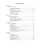
TABLE OF CONTENTS SECTION 1: GENERAL INFORMATION ................................................................................................ 1-1 1.01 1.02 1.03 1.04 1.05 1.06 1.07 1.08 Notes, Cautions and Warnings ...................................................................... Important Safety Precautions ....................................................................... Publications ..................................................................................................
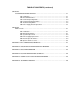
TABLE OF CONTENTS (continued) SECTION 5: CUSTOMER/OPERATOR SERVICE .................................................................................. 5-1 5.01 5.02 5.03 5.04 5.05 5.06 Introduction ................................................................................................... General Maintenance .................................................................................... Common Operating Faults ............................................................................
SECTION 1: GENERAL INFORMATION 1.01 Notes, Cautions and Warnings GASES AND FUMES Gases and fumes produced during the plasma cutting process can be dangerous and hazardous to your health. • Keep all fumes and gases from the breathing area. Keep your head out of the welding fume plume. Throughout this manual, notes, cautions, and warnings are used to highlight important information.
• Wear dry gloves and clothing. Insulate yourself from the work piece or other parts of the welding circuit. • Repair or replace all worn or damaged parts. • Extra care must be taken when the workplace is moist or damp. • Install and maintain equipment according to NEC code, refer to item 9 in Subsection 1.03, Publications. PLASMA ARC RAYS Plasma Arc Rays can injure your eyes and burn your skin. The plasma arc process produces very bright ultra violet and infra red light.
6. ANSI Standard Z49.2, FIRE PREVENTION IN THE USE OF CUTTING AND WELDING PROCESSES, obtainable from American National Standards Institute, 1430 Broadway, New York, NY 10018 ATTENTION Toute procédure pouvant résulter l’endommagement du matériel en cas de nonrespect de la procédure en question. 7. AWS Standard A6.0, WELDING AND CUTTING CONTAINERS WHICH HAVE HELD COMBUSTIBLES, obtainable from American Welding Society, 550 N.W. LeJeune Rd, Miami, FL 33126 AVERTISSEMENT 8.
• Eloignez toute fumée et gaz de votre zone de respiration. Gardez votre tête hors de la plume de fumée provenant du chalumeau. • Utilisez un appareil respiratoire à alimentation en air si l’aération fournie ne permet pas d’éliminer la fumée et les gaz. • Les sortes de gaz et de fumée provenant de l’arc de plasma dépendent du genre de métal utilisé, des revêtements se trouvant sur le métal et des différents procédés.
ultra-violets très forts. Ces rayons d’arc nuiront à vos yeux et brûleront votre peau si vous ne vous protégez pas correctement. • Pour protéger vos yeux, portez toujours un casque ou un écran de soudeur. Portez toujours des lunettes de sécurité munies de parois latérales ou des lunettes de protection ou une autre sorte de protection oculaire. • Portez des gants de soudeur et un vêtement protecteur approprié pour protéger votre peau contre les étincelles et les rayons de l’arc.
9. Norme 70 de la NFPA, CODE ELECTRIQUE NATIONAL, disponible auprès de la National Fire Protection Association, Batterymarch Park, Quincy, MA 02269 10. Norme 51B de la NFPA, LES PROCÉDÉS DE COUPE ET DE SOUDAGE, disponible auprès de la National Fire Protection Association, Batterymarch Park, Quincy, MA 02269 11.
1.07 Declaration of Conformity Manufacturer: Thermal Dynamics Corporation Address: Industrial Park #2 West Lebanon, New Hampshire 03784 USA The equipment described in this manual conforms to all applicable aspects and regulations of the ‘Low Voltage Directive’ (European Council Directive 73/23/EEC as amended by Council Directive 93/68/EEC) and to the National legislation for the enforcement of this Directive.
1.08 Statement of Warranty LIMITED WARRANTY: Thermal Dynamics® Corporation (hereinafter “Thermal”) warrants that its products will be free of defects in workmanship or material.
SECTION 2: INTRODUCTION & DESCRIPTION 2.01 Scope of Manual This manual contains descriptions, operating instructions and basic maintenance procedures for the PAK Master 150XL Plasma Cutting Power Supply (CE). Service of this equipment is restricted to properly trained personnel; unqualified personnel are strictly cautioned against attempting repairs or adjustments not covered in this manual, at the risk of voiding the Warranty. TM TM A-02072 Read this manual thoroughly.
9. CNC Interface Signals 2.03 Specifications/Design Features Start/Stop and OK-To-Move A. Power Supply Specifications The following specifications apply to the Power Supply only: 10. Coolant Pressure Internal Service Adjustable (Factory Only) 1. Front Panel Controls 130 psi (8.8 bar) at zero flow 120 - 125 psi (8.2 - 8.5 bar) at 0.6 gpm (2.3 lpm) • ON/OFF and RUN/SET Switches • Output Current Control 11. Coolant Flow Rate • Work Cable Connection 0.5 gpm (1.9 lpm) with 150 feet (45.
B. Gas Regulator/Filter Assembly Specifications 2.04 Power Supply Options and Accessories The following specifications apply to the Gas Regulator/ Filter Assembly only: NOTE Refer to Section 6, Parts Lists, for part numbers and ordering information. 1. Gas Regulator Maximum Gauge Pressure Plasma: 160 psi (11.3 bar) Secondary: 160 psi (11.3 bar) 2. Maximum Input Gas Pressure The following are accessories that are available for the Power Supply: A. High Pressure Regulators 125 psi (8.
1. 2.05 Theory Of Operation The Power Supply has a built-in parts-in-place interlock that prevents accidental torch starting when torch parts are not properly installed. A flow switch on the coolant return lead detects reduced coolant flow caused by improper torch assembly. If not satisfied, the switch interrupts power to the tip and electrode. A. Plasma Arc Cutting and Gouging Plasma is a gas which is heated to an extremely high temperature and ionized so that it becomes electrically conductive.
SECTION 3: INSTALLATION PROCEDURES least 6 inches (0.2 m) on each side for clearance . Provide sufficient clearance in front of the unit to allow access to the front panel controls (minimum 6 inches or 0.2 m). CAUTION Operation without proper air flow will inhibit proper cooling and reduce duty cycle. 3.01 Introduction NOTE 3.03 Unpacking Depending on how the system was ordered, some Power Supply options may already be installed.
NOTE WARNING Refer to subsection 3.08 for procedures on installing an earth ground for the power supply and work cable. FALLING EQUIPMENT can cause serious personal injury and equipment damage. 3.06 Gas Connections The Power Supply provides the liquid cooling and gases to support operation of the Torch. 3.05 Input Power Cable Connections NOTE WARNING Refer to the Torch Instruction Manual for information on plasma and secondary gas selection and requirements.
The following procedure is the recommended shop air connection method: 1. Connect the PLASMA Shop Air to the Two Stage Filter on the rear of the unit per the following: 1. Remove the factory installed plug fitting from the end of the Fitting in the input port (IN) of the Two Stage Air Line Filter Assembly. a. Locate the 1/4 NPT to #4 (6 mm) barbed hose fitting located inside the Torch Spare Parts Kit. b. Install the barbed fitting into the input port (IN) of the Two Stage Air Line Filter. 2.
d. Reconnect the Plasma Hose to the Plasma Regulator/Filter Assembly Inert-B Fitting. C. Using High Pressure Gas Cylinders Only NOTES e. Reconnect the Secondary Hose to the Secodary Regulator/Filter Assembly Inert-B Fitting. Refer to the manufacturer’s specifications for installation and maintenance procedures. Refer to sales literature for a listing of available high-pressure regulators and accessories. f. Install a 1/4 NPT-Insert B (right-hand) Adapter Fitting (see NOTE) into the end of the T-Fitting.
Inert B Fittings Secondary Air Regulator Assembly Plasma Air Regulator Assemby Plasma Gas Supply Hose From Gas Cylinder Access Panel Screw Latches Secondary Gas Supply Hose From Gas Cylinder Torch Leads Shield Stud Bulkhead A-02331 Figure 3-4 Connection Using Two Gas Cylinders A-02684 3.07 Connecting Torch Leads Figure 3-5 Access Panel WARNING 2. Disconnect primary power at the source before assembling or disassembling the power supply, torch parts, or torch and leads assembly.
Connect the Remote Hand Pendant and Torch Leads to the Power Supply using the following procedure: Plasma (+) Gas Secondary Gas Coolant Supply (-) Control Cable Connector 1. Open the Access Panel to gain access to the Torch Bulkhead Panel. 2. Feed the connector on the end of the Remote Hand Pendant Control Cable through the rubber boot on the front panel of the Power Supply (see NOTE).
Connect the CNC Control Cable and Torch Leads to the Power Supply using the following procedure: 1. 2. Open the Access Panel to gain access to the Torch Bulkhead Panel. Feed the connector on the end of the CNC Control Cable through the rubber boot on the front panel of the Power Supply (see NOTE). NOTE Feed the Control Cable through the rubber boot first as there will not be enough space inside the rubber boot for the connector if the Coolant and Gas Leads have been fed through the rubber boot first. 3.
6. The plasma power supply chassis is connected to the power distribution system ground as required by electrical codes. If the plasma supply is close to the cutting table (see NOTE) a second ground rod is not usually needed, in fact it could be detrimental as it can set up ground loop currents that cause interference. A-02971 3.
6. 3.09 Filling Power Supply Coolant The ambient temperature of the environment where the Power Supply will be located determines the coolant to be used. The Standard Torch Coolant supplied with the system can be used in ambient temperatures down to 10° F (-12° C). Remove the filler cap, re-fill the reservoir, place the deionizer bag into the basket in the coolant reservoir and re-install the filler cap.
INSTALLATION PROCEDURES 3-10 Manual 0-2727
2. SECTION 4: OPERATION A panel to gain access to the bulkhead area containing the torch connections. 3. 4.01 Introduction 4. 5. Lifting Eye Used to lift the Power Supply with cable and hook. B. Control Panel A. Front and Access Panel 1. Control Panel Current Control Adjustment to set the desired output current between 30-120 amps. For drag cutting applications set the control between 30 - 35 amps. The unit has an automatic fold-back circuit that limits current to 35 amps during drag cutting.
3. RUN/SET Switch 5. RUN position is used for torch operation. SET position used for setting gas pressure and purging lines. 4. Stud used to secure the torch lead shield ring lug. NOTE Used with Shielded Torch Leads only. AC Power Indicator 6. Once ON/OFF power switch is set to ON, green LED indicator will blink ON then OFF for approximately eight seconds and then stay ON. Indicates operating power is present in the unit. 5.
2. Plasma Gas Pressure Regulator/Filter Assembly 5. Pressure Regulator to adjust the plasma input gas pressure to the Power Supply. The Pressure Regulator has a built-in air line filter. Gas Input Input connections for plasma and secondary gases. Acceptable gases are as follows: Plasma Gases - Air, Nitrogen, Argon Hydrogen Secondary Gases - Air, Nitrogen, Carbon Dioxide WARNING 2 3 This unit not to be used with oxygen (O2). 6.
6. Protect eyes and press or activate torch switch. 4.04 Preparations for Operating a. Gas pre-flows starts. Follow this set-up procedure each time the system is operated: b. GAS indicator turns ON. 7. After gas pre-flow (approximately 2 seconds) WARNING a. Power Supply enabled. b. DC indicator turns ON. Disconnect primary power at the source before disassembling the power supply, torch, or torch leads. 8. Pilot arc is established. 9. Move Torch within transfer distance of workpiece. A.
Cut Surface The condition (smooth or rough) of the face of the cut. Bevel Angle The angle between the surface of the cut edge and a plane perpendicular to the surface of the plate. A perfectly perpendicular cut would result in a 0° bevel angle. A-02081 Figure 4-5 Work Cable Connection to Workpiece Top-Edge Rounding H. Torch Connection Rounding on the top edge of a cut due to wearing from the initial contact of the plasma arc on the workpiece. Check that torch is properly connected. I.
Cut Quality on Various Materials Type of Gases Air Plasma and Air Secondary Types of Material Carbon Steel Stainless Aluminum Excellent Good-Excellent Good-Excellent Gage (0.5 mm) Gage to 1 inch (0.5 mm - 25.4 mm) Excellent Good Good 1 to 1-1/2 inch (25.4 mm - 38.1 mm) Excellent Good Good Material Thickness Nitrogen Plasma Gage (0.5 mm) and Air or CO2 Gage to 1/2 inch (0.5 mm - 12.7 mm) 1/2 to 1-1/2 inch (12.7 mm - 38.1 Secondary ) Ar/H2 Plasma and Gage to 1/4 inch (0.5 mm - 6.
4. In continuous cutting applications using CO2, it is often necessary to manifold four to six cylinders together to maintain adequate flow at operating pressures. Logic PC Board B. Fold Back Feature Should the torch tip contact the workpiece or molten slag, the output current will immediately drop to 35 amps to minimize potential tip damage. A-02258 4.07 Optional Power Supply Settings The following functions can be used to tailor a system for special application requirements or unique user preferences.
Logic PC Board A-02288 1 2 SW3 Figure 4-8 Gas Pre-Flow Delay Switch SW3 Location Select the proper gas pre-flow time for the total torch lead length as shown in the following chart: Gas Pre-Flow Delay Function Pre-Flow (Seconds) 2* 3.4 4 Total Torch SW3-1 Lead Length 0 - 60 ft 1 (ON) (0 - 18.3 m) 61 - 85 ft 1 (ON) (18.6 - 25.9 m) 86 - 125 ft 0 (OFF) (26.2 - 38.
SECTION 5: CUSTOMER/OPERATOR SERVICE 5.01 Introduction This section describes maintenance procedures, basic troubleshooting and service performable by operating personnel. No other adjustments or repairs are to be attempted by other than properly trained personnel. C. Coolant Filter Assembly Cleaning The Coolant Filter Screen should be cleaned periodically. To gain access to the Coolant Filter Assembly, remove the right side panel when viewed from front of unit.
2. Disconnect the coolant input hose to the Coolant Filter Assembly. 3. Carefully lower the hose out the right side of the Power Supply and drain the coolant into an acceptable container. CAUTION Handle and dispose of the used coolant per recommended procedures. Filter Filter Holder A-02153 Coolant Filter Assembly Figure 5-2 In-Line Filter Assembly E. Coolant Level and Conductivity 1.
1. Insufficient Penetration 5. Poor Pilot Starting a. Cutting speed too fast a. Non-Genuine Thermal Dynamics Parts b. Torch tilted too much b. High coolant conductivity c. Incorrect Gas Settings 5.04 Common Operating Problems d. Metal too thick e. Worn torch parts f. WARNINGS Cutting current too low g. Non-Genuine Thermal Dynamics Parts Disconnect primary power at the source before disassembling the power supply, torch, or torch leads. 2.
D. Direction of Cut In the torches, the plasma gas stream swirls as it leaves the torch to maintain a smooth column of gas. This swirl effect results in one side of a cut being more square than the other. Viewed along the direction of travel, the right side of the cut is more square than the left (Refer to Figure 5-4). To make a square-edged cut along an inside diameter of a circle, the torch should move counterclockwise around the circle.
4. Customer's main power line fuse(s) blown a. Check main power panel fuse(s) and replace as required. D. AC Power LED ON; Fans operating; No cutting output 1. Torch not properly connected to power supply 5. Unit internal fuse blown or loose a. Check that torch leads are properly attached to power supply a. If blown, double check input voltage and replace fuse per Subsection 5.06-C. If fuse blows again, return unit to an authorized service center. 2. Shield cup not properly installed on torch a.
I. Torch cuts but not adequately M. Leaking torch connection 1. Current set too low 1. Loose torch connection a. Increase current setting. a. Check connection making sure connector is fully seated. 2. Torch is being moved too fast across workpiece a. Reduce cutting speed (refer to Instruction Manual supplied with torch). N. Weak or sputtering pilot; CD stays on during pilot 1. Plasma gas pressure too high 3. Excessive oil or moisture in torch a. Adjust pressure a.
7. To reinstall the Side Panel do the following: 5.06 Power Supply Parts Replacement a. Reconnect the ground wire to the Side Panel, if disconnected. b. Place the Side Panel onto the frame and slide the top edge under the lip on the Top Panel. WARNING c. Disconnect primary power to the system before disassembling the torch, leads, or power supply. Reinstall all the screws to secure the Side Panel. B.
Coolant Filter Assembly Flow Switch Assembly Elbow Fitting Bracket In-line Coolant Filter Assembly Coolant Hose To Pump Assembly (Filter Output) Coolant Hose (Filter Input) A-02155 Coolant Hose From Radiator Assembly Figure 5-7 Coolant Filter Replacement 3. Remove the two elbow fittings on each side of the Coolant Filter Assembly and remove the damaged assembly from the bracket. 4. Clean the old thread sealer from the threads of the elbow fittings. Figure 5-8 In-Line Coolant Filter Replacement 5.
SECTION 6: PARTS LISTS 6.01 Introduction A. Parts List Breakdown The parts list provide a breakdown of all replaceable components. The parts lists are arranged as follows: Section 6.03 System Replacement Section 6.04 Power Supply Replacement Section 6.05 Basic Replacement Parts Section 6.06 Options and Accessories NOTE Parts listed without item numbers are not shown, but may be ordered by the catalog number shown. B. Returns If a product must be returned for service, contact your authorized distributor.
6.03 System Replacement Includes: CE Power Supply with Input Power Cable, EMI Filter Assembly, Work Cable & Clamp, Coolant, Torch & Leads (as ordered), Torch Spare Parts Kit, and Operating Manual. Qty Description Catalog # CE PAK Master 150XL 380-415V Units: 1 1 With PCH 70° Hand Torch 25 ft (7.6 m) Lead Length 50 ft (15.2 m) Lead Length 1-1870-3 1-1871-3 1 1 With PCH 90° Hand Torch 25 ft (7.6 m) Lead Length 50 ft (15.
6.06 Options and Accessories Qty Description Catalog # 1 1 CNC Interface Control Cable - Used With Shielded PCM Machine Torch 25 ft (7.6 m) 50 ft (15.2 m) 8-5557 8-5558 1 Torch Guide/Circle Cutting Attachment 7-7505 1 Locking Caster Kit (2 Casters) 9-7868 1 Remote Pendant Control - Used With Unshielded PCM Machine Torch 25 ft (7.
PARTS LISTS 6-4 Manual 0-2727
APPENDIX 1: INPUT WIRING REQUIREMENTS Input Power Input Current Suggested Sizes (See Notes) 2 Voltage Freq. 3-Ph 3-Ph Fuse (Amps) (Volts) 380 (Hz) 50/60 (kVA) 29.0 (Amps) 44 3-Ph 60 Wire (mm ) 3-Ph 10 415 50/60 29.5 41 60 10 Line Voltages with Suggested Circuit Protection and Wire Sizes Based on National Electric Code and Canadian Electrical Code NOTES Refer to Local and National Codes or local authority having jurisdiction for proper wiring requirements.
APPENDIX 2: SEQUENCE OF OPERATION BLOCK DIAGRAM ACTION ACTION ACTION ACTION Close external disconnect switch. ON/OFF switch to ON. RUN/SET switch to SET. RUN/SET switch to RUN. RESULT RESULT RESULT RESULT Power to system. AC indicator blinks for 8 seconds then steady on. Fans on. Power circuit ready. Gas solenoid open, gas flows to set pressure. GAS indicator on. Gas flow stops. GAS indicator off.
APPENDIX 3: GROUNDING DIAGRAM 3-Phase Input Power Supply Work Cable Workpiece NOTES Earth Ground Work Cable must connect directly to workpiece. DO NOT connect Work Cable to earth ground and then to workpiece. Earth Ground Shielded input power cable must be grounded to earth ground at plug end.
APPENDIX 4: ROUTINE MAINTENANCE SCHEDULE This schedule applies to all types of liquid cooled plasma cutting systems. Some systems will not have all the parts listed and those checks need not be performed. NOTE The actual frequency of maintenance may need to be adjusted according to the operating environment. Daily Operational Checks or Every Six Arc Hours: 1. Check torch parts, replace if damaged. 2. Check plasma and secondary supply and pressure/flow. 3.
APPENDIX 5: POWER SUPPLY CNC INTERFACE DIAGRAM Cutting Machine CNC Cable Power Supply J22 Red START/STOP Black Blue Orange White Start Motion (OK-To-Move) Shield must be terminated at the Cutting Machine Manual 0-2727 Green Shield 3 Source 15 vdc, 10ma 4 10 Not Used 11 Not Used 12 14 2A, 125 VAC 28 vdc A-02259 A-5 APPENDIX
APPENDIX 6: SCHEMATIC DIAGRAM A-02329 APPENDIX A-6 Manual 0-2727
A-02329 Manual 0-2727 A-7 APPENDIX
APPENDIX A-8 Manual 0-2727