
Service Manual Instruction Manual

TROUBLESHOOTING
6-12 Manual 0-5282
TRANSARC 130i
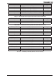
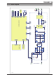
MB Header Pin Pin function signal
1 Serial display data (LOAD) 5 VDC digital
2 Serial display data & eprom (D-IN) 5 VDC digital
3 Serial diaplay data (CLK) 5 VDC digital
4 Serial display eprom (D-OUT) 5 VDC digital
5 DeadMan Switch (5V in Dead Man mode) 5 VDC digital
6 Encoder Output "A" (pulse output) 5 VDC digital
7 Encoder Output "D" (button) 5 VDC digital
8 Encoder direction 5 VDC digital
9 2T/4T push button (0v when button pushed) 5 VDC
10 MODE push button (0v when button pushed) 5 VDC
11 0V 0 VDC
12 5 VDC 5 VDC
Table 6-20: MB Header pin function (connects to J12 header on display PCB)
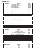
PFC Header Pin Pin function signal
1 0V 0 VDC
2 PFC OK signal, 0=PFC OK
Table 6-21: PFC Header pin function (not used)
OT1 Header Pin Pin function signal
1 thermostat
2 thermostat
Table 6-22: OT1 Header pin function (connects to thermostats)
OT2 Header Pin Pin function signal
1 Link to 0V
2 0V 0VDC
Table 6-23: OT2 Header pin function (link)
HF Header Pin Pin function signal
1 0 VDC 0 VDC
2 HF control line (0V = HF OFF)
3 HF control line 120/240 (0V=240VAC supply) 0 VDC
4 0 VDC 24 VDC
Table 6-24: HF Header pin function (not used)
DRIVE Header Pin Pin function signal
1 +15 VDC 15 VDC
2 IGBT 1 pwm drive signal, 15V P-P square ware 15 VDC pk
3 IGBT 2 pwm drive signal, 15V P-P square ware 15 VDC pk
4 IGBT 2 pwm drive signal, 15V P-P square ware 15 VDC pk
5 IGBT 1 pwm drive signal, 15V P-P square ware 15 VDC pk
6 Rectified secondary of current transformer TR8 15 VDC pk
7 0 VDC 0 VDC
Table 6-25: DRIVE Header pin function (connects to IN header on inverter PCB)
SOURCE Header Pin Pin function signal
1 +24 VDC 24 VDC
2 0 VDC 0 VDC
3 -24 VDC -24 VDC
Table 6-26: SOURCE Header pin function (connects to DY2 header on inverter PCB)