
Owner manual


ULTRA-CUT 100 XT
Manual 0-5272 APPENDIX A-55
PWR Present
• Whenpowerisrstappliedtotheinverter(contactorclosed)CCMchecksforpresenceofthe+12Vbias
ontheInverterControlandFaultboard.Ifnotpresentwillsetcodesintherangeof265-270.
IS_ID (A, B, or C)
VAC_SEL (A or B)
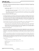
201 Missing AC Phase
The System Bias Supply board contains circuits to detect if one of the 3 AC input phases is missing. Along with
thatitcanalsodetectiftheACvoltageistoolowortoohigh.Threephasevoltageissuppliedfromtheinput
terminalsthroughtheON/OFFSwitch/circuitbreakerCB1totheSystemBiasboard.TheSystemBiascan
operate on any 2 of the 3 phases to supply control power and fault detection.
1
2
3
4
5
6
7
8
9
10
11
12
13
14
J62
1
2
3
4
5
6
7
8
9
10
11
12
13
14
J27
GND
+V
1
2
4
3
HCPL-817
U?
Missing Phase a
Missing Phase b
GND
To CPU PCB
J29-16
Missing Phase
I/O PCB
SYSTEM BIAS PCB
CB1
ON / OFF
F2
F1 J60-9,18
J60-5,14
J60-1,10
3 phase AC
Art # 12310
Normally when the phase is not missing the transistor is on which turns on the opto-isolator making the signal
“MissingPhase”low.
Causesfor201,missingphasecode.Codesaredisplayedtwodifferentways,withan“L”meaning“Latched”
or“Last”,beforethenumbermeaningitwasaproblembutisn’trightnoworwithan“E”meaningtheproblem
exists now.
L201 :
Most likely cause is an intermittent problem with the incoming power or possibly a loose connection on the
power cord at the back or the Ultra-Cut or Auto-Cut plasma supply.
E201:
• Phasemissingfromthewallfusebox,blownfuse.
• F1orF2,8A500Vslowblowfusesblown.
• CB1onephaseopen.
• SystemBiasboarddefective.
• I/Oboarddefective.
Troubleshooting:
1. SystemBiasboardhasaredLED,D3,thatlightsifitdetectsamissingphase.IfD3ison,checkJ60forall3
phases.
a. Ifall3phasesarenotpresentatJ60checkforincomingpower,thentheF1&F2fuses.FinallytheCB1.
b. Ifall3phasespresentandaboutequalvoltagethenchangetheSystemBiasboard.
2. IfD3,MissingPhaseLED,isnotoncheckforvoltageatJ27-3&4ontheCCM.Normalvoltage,withno
missingphase,atJ27(orJ62ontheSystemBiasboard)pin3andpin4,relativetoI/OPCBground.(TP1)
shouldbebetween10-14VDCwithpin3beingacouplevoltshigherthanpin4.Ifthisisnormal,problem
may be in the CCM.
3. IfthevoltageatJ27-3&4ishigherthan10-14VDCandupto20-24VDC,makethesamemeasurementat
J62pin4.Ifstillhighthereandyouhaveconrmedall3phasesarepresentatJ60thentheSystemBiasis
defective.
4. IfthevoltageatJ62-4isnothighthewiresbetweenJ27andJ62maybebroken.