
Owner manual


ULTRA-CUT 100 XT
A-44 APPENDIX Manual 0-5272
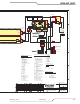
The AC Suppression PCB has capacitors and other transient suppression components to protect the system from
transientsontheAClines.ItalsoprovidespowerfortheneonACpresentindicatorswhichilluminatewhenAC
powerisconnectedevenwithON-OFFswitch,CB1,off.
Differences between various models.
Auto-Cut200or300XTunitsusethebasicgascontrol/arcstartcircuitsconsistingofsinglegasinlets,oneforPlasma,
one for Gas Shield and one for water inlet, optional for AC 200 XT, for H2O Mist shield. There is a pressure regula-
torandgaugeforeachgasinletandwaterowmeter/controlwhentheH2OMistoptionisused.All3areturned
on/offwithcontrolsolenoids.Changinggastypesrequiresconnectingdifferentgassestotherearpanelandsetting
thegasswitchontherearpaneltomatchtheplasmagastype.Thereisnoseparatepilot(Preow)gasatthistime.
TheAuto-CutArcstarteristheconventionalsparkgaptypewithwatercooledcoilthatwe’veusedforseveralyears.
ThisarcstarterinjectstheHFontothetorchelectrodeviathenegativeleadwiththereturnviathetipandpilotlead.
The Ultra-Cut XT units use the remote arc starter, RAS 1000 XT. In place of the spark gap the RAS 1000 XT uses a
solidstateignitionmoduletocreatetheHFpulseswhichareinjectedontothetipandreturnviatheelectrode,the
opposite direction of that used in the Auto-Cut, Auto-Cut XT and the older RAS 1000 used with the Ultra-Cut units.
The AC 200 XT had the gas control and arc starter built into the main enclosure in the area that is used for the top
invertermoduleinotherunitsofthisfamily.TheAC 300 XThasaseparategascontrol/ArcStarterthatsitsontop
ofthemainenclosureverysimilartotheGCM1000ofourearlierAuto-Cutmodels.ItisinfactcalledaGCM 1000
XT.BothAuto-CutXTmodelshaveananalogcurrentcontrol(Potentiometer).Onthefrontpanelofthemainunit
fortheAC200XTandintheupperbox,theGCM1000XT,fortheAC300XTversion.Ineithercasetheamperage
setting is displayed on the front panel digital display.
BothAuto-Cutmodelshavethegasmodeswitchontherear,fortheAC300XTnexttothegasinletsoftheGCM
1000XT.OntheAC200XTit’sneartheconnectors,fuses&circuitbreakers.Theswitchshouldbesetaccording
tothetypeofgas,AIR/O2orN2,H35orothernon-oxidizinggas,beingusedfortheplasma.
IntheAC200XTthePilotboardismountedontheuppersectionofthesecondinvertermodule(IM#2)the½mod-
ule,intheplaceofthesecondor“B”sectionifitwasafullmodule.TheAC300XTandallUltra-CutXTmodels
havethePilotboardontheoppositesidefromtheinverters,the“circuitbreaker”side,intheupperrearbehindthe
CCM module. Refer to the Replacement Parts section of the manual for illustrations showing the locations.
Ultra-CutXTunits,100,200,300&400AunitsallcanuseeithertheGCM 2010 “manual”GascontrolortheDFC
3000 Auto Gas Control. These gas controls remain unchanged from earlier Ultra-Cut units.
Ultra-CutXTunitsusethesameowswitch,FS1,astheAuto-CutXTunitstodetectandpreventoperationwhen
coolantowisbelowtheminimumof0.75GPM(2.8l/m).However,theUltra-CutXTsincludeacoolantow
sensor,FL1,whichalsomeasurestheowandcandetectiftherearegasbubblesinthecoolantwhichcanreduce
consumablepartlife.DetectingbubblesorlowowfromFL1willNOTpreventcuttingbutwillshowacodeasa
warningthatsomethingisnotright.ThecodeisE406.
Ultra-CutXTshavestandardconsumablesforcuttingcurrentslowerthanthoseusedforAuto-CutXT,15Avs.55A
aswellasmarkingatlowercurrents.Toimproveoperationattheselowercurrentsanadditionaloutputinductor,
L1,isaddedinserieswiththe1stinvertersection(IM#1A).