
Owner manual


ULTRA-CUT 100 XT
Manual0-5272 APPENDIX A-43
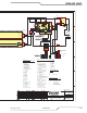
section(INV1A,INV1B,etc.).A100AunitwillonlyhaveribboncablesinJ31&J32;a200AwillhaveJ31-J33lled
withtheothersempty.300AwillhaveJ34missingwiththeotherslled.
Other boards in the system include the System Bias Supply, the Relay & Interface PCB, Display PCB, Pilot PCB
and AC Suppression PCB.TheCCMhas2boards,theI/O(input/output)andtheCPU(centralprocessingunit)
board.TheCEunitswillalsohaveoneormoreEMIFilterboardsontheinputpower.
System Bias supply PCBispoweredfromthe3phaseACinputandworksfromabout150Vtoover600Vcovering
allthenormalvoltageranges.Itcanoperatefrom2phases(singlephase)soitstillprovidesbiaspowerandcan
reportafaultifaphaseismissing.Thesupply’soutputis24VDCwhichpowerstheRelayboard,theDisplay,the
Pilot board and the 2 boards in the CCM. System Bias also contains circuits to detect missing phase and determine
iftheACvoltageiswithinthecorrectrange,nottoohighortoolow.ItalsosignalstotheCCMwhatvoltagethe
unitisconguredfor.TheSystemBiassupplyPCBincludesarelay,K1,whichonlyappliesvoltagetoAuxiliary
transformer,T1,primarywhentheinputvoltageisinthecorrectrange.
The Relay and Interface PCB Accepts and distributed the output of the Aux Transformer. It has relay to control
the pump, fans, input contactors, the Arc Starter and the Inrush relays. A circuit on the Relay board accepts input
fromtheWorkcurrentsensor,HCT1,andPilotcurrentsensor(onthePilotPCB)andsendstheEnablesignaltothe
PilotboardsIGBTswitchesviatheJ3toJ42ribboncable.OtherinputsontheRelayboardincludethosefromthe
NegativeTemperatureCoefcient(NTC)ambientandcoolanttemperaturesensors.Coolanttanklevelswitchand
coolantowswitch,whichdeterminesiftheowisabovetherequiredminimumrate,alsosendsignalstotheRelay
Board.Ultra-CutunitsincludeaowsensorwhoseoutputtotheRelayBoardisaseriesofpulseswhosefrequency
indicatestheowrateandcandetectthepresenceofgasbubblesinthecoolant.AllthesesignalspasstotheCCM
viaa40conductorribboncablegoingtotheCCMI/Oboard.
The Display BoardHasLEDsforAC,TEMP,GAS&DC.Italsohasa4digit7segmentdisplayforstatusandfault
information.ACLEDindicatestheinputcontactorstotheinvertershavebeencommandedtoclose,butdoesnot
meantheyareclosed.TEMPmeansoneormoreinvertersorthecoolanthasexceededtheallowedtemperature.
GASmeansgasisowingandcoolantowisOK.DCmeanstheinvertersoutputvoltageisabove60VDC.
Therstdigitofthe7segmentdisplayshowstheletter,“C”;“E”;“L”orisblank.Duringtheinitialpowerupse-
quencetheletter“C”followedbytheother3digits,indicatestheCCMcoderevision.StatusorFaultcodeswhich
mayoccurduringthepowerupsequenceoranytimethereafterareprecededbyletters“E”foranactivefaultor
“L”fora“latched”or“last”faultthatstoppedtheprocessbutisnolongeractive.WhenthereisnoFaultoractive
Statuscode,theoutputcurrentsettingisdisplayedwiththerstdigitblank.IfthesystemisanUltra-CutXTusing
theAutoGasControl,DFC3000,thedisplaywillshow“0”untilaprocesshasbeenloaded.Ifthereisafaultor
other status showing the display will alternate between the current setting and the fault.
The Pilot PCB contains a pair of parallel IGBT transistors working as an electronic switch to connect and disconnect
thetorchtipfromthe1stinvertersection.
WhenthepilotelectronicswitchisclosedandthepilotisignitedbytheArcStarter,currentfromthe1stsection
owsbetweenelectrodeandtip.Thenastransferbegins,asmallcurrentfromthe2ndinverterowsfromelec-
trodetowork.Whentransferisdetectedthepilotswitchisopenedandcurrentfromthe1stsectionisfreetoow
to the work through the diode which is also on the Pilot board. The Pilot PCB also contains a pilot current sensor
todetectandmeasurethelevelofpilotcurrent.Additionalresistor/capacitor(RC)circuitsonthepilotPCBassist
and stabilize the pilot and transferred arcs.
Art # 12301