
Manual

ULTRA-CUT 100 XT
3-24 INSTALLATION Manual 0-5303
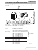
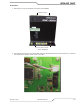
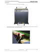
3.16 DPC-3000 Gas Pressure Control Installation
TheDPC-3000GasControlmustbeinstalledinasuitablelocationclosetotheTorchsuchasthegantry.Theunit
mustbemountedtoaathorizontalsurface.IftheModuleismountedtoanysupportsubjecttovibrationormotion,
the installer must fasten the module to the support securely.
TheModuleshouldbelocatedasfarawayaspossiblefromtheArcStarterduetopossibleelectromagneticinter-
ference.ItisacceptabletolocatethecontrolcableinthesametrackasthecablesfromtheArcStarterandaway
from torch leads.
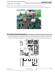
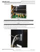
TheModuleincludesfeetwhichliftthebottompaneloffthemountingsurface.Louversonthebackpanelofthe
modulemustremainunblocked,forthefreepassageofventilatingair.
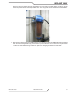
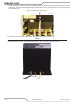
TheModulealsocomeswithnonmetallicisolationgrommetsformounting.Thesemustbeusedinallfourmount-
ingslotstoraisetheModulesothereisnometaltometalcontactbetweentheModuleandthemountingsurface
inordertoreducethechanceofEMIinterference.
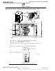
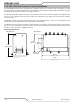
Mounting Dimensions
10.90 in
[276.86 mm]
DPC-3000 Profile
4.00 in
[101.6 mm]
6.64in
[168.7mm]
11.00 in
[279.4 mm]
10.45 in
[265.4 mm]
.30 in
[7.62mm]
DPC-3000 Top
Art # A-09143