
Manual

ULTRA-CUT 100 XT
3-22 INSTALLATION Manual 0-5303
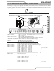
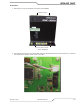
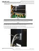
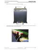
3. Attach all hoses and cables to the front of the DMC-3000 except the Fiber Optic cable which will be covered
a little later. Avoid turning any ttings already mounted in the unit by placing a wrench on it before tightening
the hose tting to it.
Art # A-09141_AB
NOTE
Argon must be used for the “Marking” gas. If replacing existing ttings in the base, apply thread sealant
to the tting threads, according to manufacturer’s instructions. Do not use Teon tape as a thread sealer,
as small particles of the tape may break off and block the small air passages in the torch.
NOTE
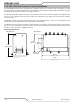
If you need to replace a gas or water tting all inlets and outlets of the aluminum manifold are 1/4” NPT
(United States National Pipe Thread) into which are screwed the various adapters.
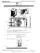
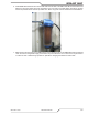
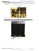
4. Connect the ground cable to rear of DMC-3000 shown in previous illustration.
5. Connect Control cable from the Power Supply to J56 on the front of the DMC-3000 as shown below. The
Fiber Optic cable will be covered a little later.
Art # A-09142_AB