
Manual

ULTRA-CUT 100 XT
3-20 INSTALLATION Manual 0-5303
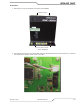
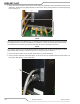
NOTE
There are holes added in the rear panel for customer wiring. This, rather than the one in the CCM will be
the preferred place for customer added wiring (and strain relief) for connections to height controls, etc..
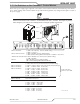
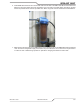
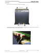
3.15 DMC-3000 Gas Manifold Control Installation
TheDMC-3000GasControlmustbeinstalledinasuitablelocationwhereitiseasilyaccessibletothesystemop-
erator.Theunitmustbemountedtoaathorizontalsurface.IftheModuleismountedtoanysupportsubjectto
vibrationormotion,theinstallermustfastenthemoduletothesupportsecurely.
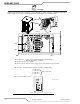
TheModuleshouldbelocatedasfarawayaspossiblefromtheArcStarterduetopossibleelectromagneticinter-
ference.ItisacceptabletolocatethecontrolcableinthesametrackasthecablesfromtheArcStarterandaway
from torch leads.
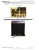
TheModuleincludesfeetwhichliftthebottompanelofthemountingsurface.Louversonthebackpanelofthe
modulemustremainunblocked,forthefreepassageofventilatingair.
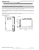
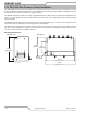
Mounting Dimensions
5.00 in
[127.0 mm]
7.08 in
[179.8 mm]
12.18 in
[309.4 mm]
11.44 in
[290.6 mm]
.30 in
[7.62 mm]
DMC-3000 Top
13.60 in
[345.6 mm]
DMC-3000 Profile
Art # A-09459