
Manual

ULTRA-CUT 100 XT
Manual 0-5303 INSTALLATION 3-7
A. Electromagnetic Interference (EMI)
Pilotarcstartinggeneratesacertainamountofelectromagneticinterference(EMI),commonlycalledRFnoise.This
RFnoisemayinterferewithotherelectronicequipmentsuchasCNCcontrollers,remotecontrols,heightcontrollers,
etc.TominimizeRFinterference,followthesegroundingprocedureswheninstallingmechanizedsystems:
B. Grounding
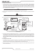
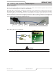
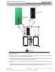
1. Thepreferredgroundingarrangementisasinglepointor“Star”ground.Thesinglepoint,usuallyonthecutting
table,isconnectedwith1/0AWG(European50mm
2
)orlargerwiretoagoodearthground(measuringless
than3ohms;anidealgroundmeasures1ohmorless.Refertoparagraph‘C’,CreatingAnEarthGround.The
groundrodmustbeplacedascloseaspossibletothecuttingtable,ideallylessthan10ft(3.0m),butnomore
than20ft(6.1m)fromthecuttingtable.
NOTE
All ground wires should be as short as possible. Long wires will have increased resistance to RF fre-
quencies. Smaller diameter wire has increased resistance to RF frequencies, so using a larger diameter
wire is better.
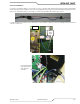
2. Groundingforcomponentsmountedonthecuttingtable(CNCcontrollers,heightcontrollers,plasmaremote
controls,etc.)shouldfollowthemanufacturer’srecommendationsforwiresize,type,andconnectionpointloca-
tions.
ForThermalDynamicscomponents(exceptRemoteArcStarterandGasControlModule)itisrecommended
touseaminimumof10AWG(European6mm
2
)wireoratcopperbraidwithcrosssectionequaltoorgreater
than10AWGconnectedtothecuttingtableframe.TheRemoteArcStarteruses1/0earthgroundwireandthe
GasControlModuleshoulduseminimum#4AWGwire.Theconnectionpointmustbetocleanbaremetal;
rustandpaintmakepoorconnections.Forallcomponents,wireslargerthantherecommendedminimumcan
be used and may improve noise protection.
3. Thecuttingmachineframeisthenconnectedtothe“Star”pointusing1/0AWG(European50mm
2
)orlarger
wire.
4. Theplasmapowersupplyworkcable(seeNOTE)isconnectedtothecuttingtableatthesinglepoint“Star”
ground.
NOTE
Do Not connect the work cable directly to the ground rod. Do not coil up excess ground or power cables.
Cut to proper length and reterminate as needed.
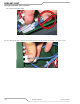
5. Makesureworkcableandgroundcablesareproperlyconnected.Theworkcablemusthaveasolidconnec-
tiontothecuttingtable.Theworkandgroundconnectionsmustbefreefromrust,dirt,grease,oilandpaint.If
necessarygrindorsanddowntobaremetal.Uselockwasherstokeeptheconnectionstight.Usingelectrical
jointcompoundtopreventcorrosionisalsorecommended.
6. Theplasmapowersupplychassisisconnectedtothepowerdistributionsystemgroundasrequiredbyelectrical
codes.Iftheplasmasupplyisclosetothecuttingtable(seeNOTE)asecondgroundrodisnotusuallyneeded,
in fact it could be detrimental as it can set up ground loop currents that cause interference.
Whentheplasmapowersupplyisfarawayfromthegroundrodandinterferenceisexperienced,itmayhelpto
installasecondearthgroundrodnexttotheplasmapowersupply.Theplasmapowersupplychassiswould
then be connected to this ground rod.
NOTE
It is recommended that the Plasma Power Supply be within 20 - 30 ft (6.1 – 9.1 m) of the cutting table,
if possible.
7. Theplasmacontrolcableshouldbeshieldedwiththeshieldconnectedonlyatthecuttingmachineend.Con-
nectingtheshieldatbothendswillallowgroundloopcurrentswhichmaycausemoreinterferencethanwithno
shield at all.