
Manual

ULTRA-CUT 100 XT
3-6 INSTALLATION Manual 0-5303
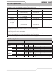
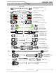
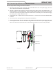
3.07 Connect Work Cable and Pilot and Negative Leads
1. Remove the output power cover to the left of the coolant lter at the rear of the power supply. To do this
remove the two screws then lift up and pull away.
2. Routetheendsoftheworkcable,pilotandnegative/torchleadsupwardthroughtheleadsstrainreliefatthe
bottom edge of the left rear panel.
3. Refertotheillustration.Connecttheleadsasshown.Tightensecurely.Donotovertighten.
Art # A-11533
Pilot
Work Cable
Torch
+
-
4. Reinstall the cover on the power supply. Snug the hardware securely by hand. Do not overtighten.
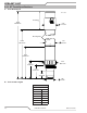
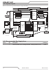
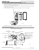
3.08 Ground Connections
0 - 10 ft (0 - 3 m) Ideal
20 ft (6 m) Maximum
1/0
Ground Cable
Power Supply
‘Star’
Ground
Earth Ground
Rod
See
Manufacturer
CNC
Device
Torch
Cutting Table
Cutting Machine / Gantry
3/0 Work Cable
Remote Arc
Starter (RAS-1000)
Star Ground on Cutting Table
Note: The gas control module can
be mounted on top of the power
supply.
If it is, it should be grounded
directly to the power supply with
#4 AWG ground, (F).
Any location requires grounding
the power supply to the
‘Star’ ground with the 1/0
Ground Cable (F1).
Gas Control Module
Primary location
#4 AWG
Ground
(F)
Customer supplied
1/0
Ground Cable
(F1)
Art # A-11875
1/0 Ground Cable