
Manual

ULTRA-CUT 100 XT
A-58 APPENDIX Manual 0-5303
202-204 Not used. Reserved codes from the earlier product.
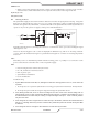
205 DC Output Low
DC output (voltage) low means one or more inverter sections are enabled but the output voltage is below a
preset voltage. Shortly after receiving the Start signal from the CNC, but before the end of preflow, both sections
of IM#1 are enabled and CCM measures the power supply output voltage between negative (Torch) to positive
(Work) at the output terminals. If this is less than a set value during preflow or if at any time during piloting
or cutting it drops to below that value for a short time, the inverters are shut off and code 205 is set. 205 will
almost always be indicated as an “L”, not an “E” fault because as soon as it’s detected the inverters are shut off
and so no longer have the fault of low output voltage. Currently the low voltage value is -60VDC.
Causes of 205 code can include shorts outside the plasma power supply, shorts inside the plasma power supply
and measurement errors.
a. Short external to the plasma power supply:
• ThenegativeleadgoesfromtherearofthepowersupplytotheremotearcstarterortotheGCM1000XT
in the case of the AC 3000 XT.
o Cable pinched in or exiting the power track
o Short inside the Arc Starter such as a wire coming loose and grounding to the chassis.
o Short inside the torch mounting tube.
• Troubleshootforexternalnegativeleadshortsbyremovingtheleadfromtherearofthepowersupply
and try to start. It won’t start but if you get the same 205 code the problem is inside the unit.
b. Short inside the supply:
• AlltheinvertersoutputsexceptthatofIM1Aareinparallel.Ifanyinverter’soutputisshorteditwill
appear as a short across the power supply output.
Troubleshoot by removing all (or one at a time) of the inverter output connectors except those on IM1A.
Then apply Start to the unit. If it starts now one of the other inverters had shorted output. To find
the defective one reconnect one at a time until the fault reappears.
206 Not used. Reserved codes from the earlier product.
207 Unexpected Current in the Work Lead.
HCT1, a Hall Effect current sensor on the positive (work buss bar) measures the work lead current. Inverter
section 1A is enabled during preflow time but there should be no current in the work lead before the pilot is
ignited and before the arc is transferred to the work. If current greater than 8A is detected before or during
preflow something is wrong.
1. 207 code before START applied:
• Defectiveworkcurrentsensor,HCT1.
• DefectiveRelayPCB
• DefectiveCCM
Defective Sensor
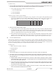
• Theworkcurrentsensor,HCT1,receivespower,+15VDCand-15VDCfromtheRelayPCB.Bothmust
be present for the sensor to work properly. Measure between Relay PCB TP1 (or J1-4) to J1-1 for +15VDC
and to J1-2 for -15VDC.
• Ifeither+or–15VDCnotpresentremovetheJ1connectorandrepeatthemeasurementatJ1-1&2onthe
Relay board. If the voltage is now present the sensor is defective or shorted (the harness may be shorted).
If voltages still not present, the Relay board is defective.