
Manual

ULTRA-CUT 100 XT
Manual 0-5303 SPECIFICATIONS 2-1
SECTION 2: SPECIFICATIONS
2.01 General Description Of The System
A typical Ultra-Cut XT™system configuration includes:
• OnePowerSupply
• RemoteArcStarter
• GasControl-DigitalmanifoldControl(DMC)
• GasControl-DigitalPressureControl(DPC)
• PrecisionPlasmaCuttingTorch
• SetOfConnectingLeads
• TorchSparePartsKit
• TouchScreenControl(TSC),Optional
• HeatExchanger,Optional
The components are connected at installation.
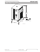
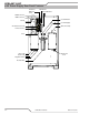
2.02 Plasma Power Supply
Thepowersupplyprovidesthenecessarycurrentforcuttingoperations.Thepowersupplyalsomonitorssystem
performance,andcoolsandcirculatestheliquidcoolantforthetorchandleads.
2.03 Remote Arc Starter
ThisunitproducesatemporaryHFpulsetostartthepilotarc.Thepilotarccreatesapathforthemainarctotransfer
tothework.Whenthemainarcisestablished,thepilotarcshutsoff.
2.04 Gas Control Module
Thismoduleallowsremotesettingofgasselection,pressures,andowstogetherwithsettingofcuttingcurrent.