
Manual

ULTRA-CUT 100 XT
Manual 0-5303 APPENDIX A-45
will only have ribbon cables in J31 & J32; a 200A will have J31-J33 lled with the others empty. 300A will have J34
missing with the others lled.
Other boards in the system include the System Bias Supply, the Relay&InterfacePCB,DisplayPCB,PilotPCB
and AC Suppression PCB. The CCM has 2 boards, the I/O (input/output) and the CPU (central processing unit)
board. The CE units will also have one or more EMI Filter boards on the input power.
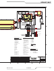
System Bias supply PCB is powered from the 3 phase AC input and works from about 150V to over 600V covering
all the normal voltage ranges. It can operate from 2 phases (single phase) so it still provides bias power and can
report a fault if a phase is missing. The supply’s output is 24 VDC which powers the Relay board, the Display, the
Pilot board and the 2 boards in the CCM. System Bias also contains circuits to detect missing phase and determine
if the AC voltage is within the correct range, not too high or too low. It also signals to the CCM what voltage the
unit is congured for. The System Bias supply PCB includes a relay, K1, which only applies voltage to Auxiliary
transformer, T1, primary when the input voltage is in the correct range.
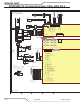
The Relay and Interface PCB Accepts and distributed the output of the Aux Transformer. It has relay to control
the pump, fans, input contactors, the Arc Starter and the Inrush relays. A circuit on the Relay board accepts input
from the Work current sensor, HCT1, and Pilot current sensor (on the Pilot PCB) and sends the Enable signal to
the Pilot boards IGBT switches via the J3 to J42 ribbon cable. Other inputs on the Relay board include those from
the Negative Temperature Coefcient (NTC) ambient and coolant temperature sensors. Coolant tank level switch
and coolant ow switch, which determines if the ow is above the required minimum rate, also send signals to the
Relay Board. Ultra-Cut units include a ow sensor whose output to the Relay Board is a series of pulses whose
frequency indicates the ow rate and can detect the presence of gas bubbles in the coolant. All these signals pass
to the CCM via a 40 conductor ribbon cable going to the CCM I/O board.
The Display Board Has LEDs for AC, TEMP, GAS & DC. It also has a 4 digit 7 segment display for status and fault
information. AC LED indicates the input contactors to the inverters have been commanded to close, but does not
mean they are closed. TEMP means one or more inverters or the coolant has exceeded the allowed temperature.
GAS means gas is owing and coolant ow is OK. DC means the inverters output voltage is above 60 VDC.
The rst digit of the 7 segment display shows the letter, “C”; “E”; “L” or is blank. During the initial power up sequence
the letter “C” followed by the other 3 digits, indicates the CCM code revision. Status or Fault codes which may
occur during the power up sequence or any time thereafter are preceded by letters “E” for an active fault or “L” for
a “latched” or “last” fault that stopped the process but is no longer active. When there is no Fault or active Status
code, the output current setting is displayed with the rst digit blank. If the system is an Ultra-Cut XT using the Auto
Gas Control, DFC 3000, the display will show “0” until a process has been loaded. If there is a fault or other status
showing the display will alternate between the current setting and the fault.
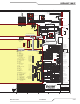
The Pilot PCB contains a pair of parallel IGBT transistors working as an electronic switch to connect and disconnect
the torch tip from the 1st inverter section.
When the pilot electronic switch is closed and the pilot is ignited by the Arc Starter, current from the 1st section ows
between electrode and tip. Then as transfer begins, a small current from the 2nd inverter ows from electrode to
work. When transfer is detected the pilot switch is opened and current from the 1st section is free to ow to the work
through the diode which is also on the Pilot board. The Pilot PCB also contains a pilot current sensor to detect and
measure the level of pilot current. Additional resistor/capacitor (RC) circuits on the pilot PCB assist and stabilize
the pilot and transferred arcs.
Art # 12301