
Manual

ULTRA-CUT 100 XT
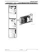
A-6 APPENDIX Manual 0-5303
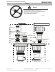
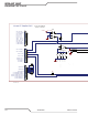
SimpliedCNCCircuit.
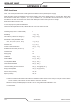
Art # A-11579
Art # A-11579
15 - K ey Plug
1
2
3
4
5
6
7
8
9
10
11
12
13
14
15
16
17
18
19
20
J22
1
2
3
4
5
6
7
8
9
10
11
12
13
14
15
16
17
18
J21
GND
GND
8- COM M Ref (1K Ohm)
* Used with Mom en tary C NC Start SW
1
2
3
4
5
6
7
8
9
10
11
12
13
14
15
16
17
18
19
20
21
22
23
24
25
26
27
28
29
30
31
32
33
34
35
36
37
J15-CNC
4- / CN C Start (-)
6- D ivided A rc V (+)
5- D ivided A rc V (-)
12- OK to M ove (-)
14- OK to M ove (+)
7- / Preflow ON (+)
9- / Preflow ON (-)
30- Remote CC (analog)
29- Remote CC Pot High
31- Remote CC Pot L ow
16- / Hold Start (+)
17- / Hold Start (-)
3- / CN C Start (+)
21- / Plasma M ark (+)
22- / Plasma M ark (-)
23- / Cut Expanded M etal (+)
24- / Cut Expanded M etal (-)
25- / CNC Plasma Enable (+)
26- / CNC Plasma Enable (-)
32- Stop SW (momentary) *
33- Stop SW R
et
34- Pilot is ON (a)
35- Pilot is ON (b)
36- Spar
e OUT #1 (a)
37- Spare OUT #1 (b)
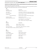
(132)
(133)
(137)
(132)
(133)
C hassi s
(136)
(134)
(135)
(139)
(138)
(134)
(135)
(136)
(137)
(138)
(139)
(140)
(141)
(143)
(142)
(144)
(145)
(146)
(148)
(140)
(141)
(142)
(143)
(144)
(145)
(146)
(148)
(147)
(149)
(150)
(147)
(149)
(150)
(151)
(152)
(153)
(154)
(155)
(156)
(151)
(152)
(153)
(154)
(155)
(156)
(157)
(158)
(159)
(157)
(158)
(159)
PSR
SPA RE #1a
J15-1 to chassis used for
SC-11 cable shield
+10V (CC Pot Hi )
CC Pot W iper
CC Pot L ow
Di v A rc V (+)
Di v A rc V (-)
/Start - Stop (+)
/Start - Stop (-)
Stop Mo m NC
OK2 (cont act)
/ CNC Enabl e (+)
/ CNC Enabl e (-)
OK2 (cont act)
OK to M OV E (+)
OK to M OV E (-)
PILOT is ON
PILOT is ON
Prefl ow ON (+)
Prefl ow ON (-)
Hol d Start (-)
Hol d Start (+)
/ Plasma M arki ng (+)
/ Plasma M arki ng (-)
/ Corner Current Reducti on (-)
/ Corner Current Reducti on (+)
/ Cut Ex panded M etal (-)
/ Cut Ex panded M etal (+)
Spare #2 NO
Spare #2 NC
Spare #1b NO
1
2
3
4
5
6
7
8
9
10
11
12
TB2
1
2
3
4
5
6
7
8
9
10
11
12
TB1
1
2
3
4
5
6
7
8
9
10
11
12
TB2
+10V
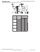
ALL SW OFF f or 5 0 : 1 ( de f a u l t )
SW12 A ( 1) ON = 1 6 . 7: 1 ( SC- 1 1 )
SW12 B ( 2) ON = 3 0 : 1
SW12 C ( 3 ) ON = 40 : 1
1 8
SW 12A
V OLTA GE DIV ID ER
2 7
SW 12B
3 6
SW 12C
4 5
SW 12D
-
4
+
3
5
B
D C VO LT S
C ONTA CT S
18 V D C or Con tacts
SW6B
SW6A
OK TO MOVE SELECT
+18VDC
OK
Ult racut X T Simplified CNC
1
2
3
4
5
6
7
8
9
10
11
12
13
14
J54 - Rem ote HM I & CN C CO M M
7 - K ey Pl ug
1 - 24 V AC
2 - 24 V AC Re t
8 - Tx +
12 - Tx -
13 - Rx +
14 - Rx -
9 - GND
10 - GN D
RS 485
/ 422
Comm
(115)
(116)
(117)
(118)
(119)
(120)
Harness to CPU PCB
(100)
(108)
(109)
6-H M I Plasma Enabl e SW
5-H M I Plasma Enabl e SW
3- Jumper to 24 V AC
(101)
(102)
Harness to Relay PCB
J15-13 connects SC-11
chassis to PS chassis.
The COM M Ref at pin
8 is also for the SC-11