TP9KF-TUX Two-Post Floor Plate Lift (Symmetric) 9,000 lbs. Capacity (2,250 lbs.
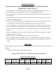
IMPORTANT NOTES READ THE INSTALLATION AND OPERATION MANUAL IN ITS ENTIRETY BEFORE ATTEMPTING TO INSTALL THE LIFT. · Do not install this lift on any surface other than concrete, conforming to minimum specifications. · Do not install this lift over expansion joints or cracks. Check with building architect. · Do not install this lift on a second floor with a basement beneath without written authorization from building architect.
PREPARATION The installation of this lift is relatively simple and can be accomplished by 2 men in a few hours. The following tools and equipment are needed: · 12 quarts of Non-Detergent / Non-Foaming Hydraulic Oil - SAE-10, AW 32 or equivalent · Chalk line and 12’ Tape Measure · 4ft. Level · Rotary Hammer Drill with 3/4” Masonry Drill Bit.
4 TP9KF-TUX Mar 2019
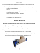
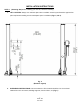
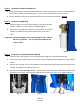
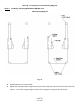
INSTALLATION INSTRUCTIONS STEP 1: 1. (Selecting Site) Before installing your new lift, check the following: LIFT LOCATION: Always use architects plans when available. Check layout dimension against floor plan requirements making sure that adequate space is available (Figs. 2, 3 & 4). Fig. 2 (Elevation Layout) 2. OVERHEAD OBSTRUCTIONS: The area where the lift is located should be free of overhead obstructions such as heaters, building supports, electrical lines, etc. (Fig 2.
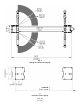
Fig. 3 (Swing Arm & Column Layout) (134-5/8”) Fig.
3. DEFECTIVE CONCRETE: Visually inspect the site where the lifts will be installed and check for cracked or defective concrete. (Details on Page 4) 4. FLOOR REQUIREMENTS: The lift should be installed on a 3000 PSI concrete with minimum of 4-1/4” thickness. The Floor should be level with-in gradients of ≦1/4” within area of the two columns = 135” x 18”). (See Details for Foundation Anchoring Requirements & Anchoring Tips on Page 4) STEP 2: (Unloading & Unpacking) 1.
STEP 4: 1. (Installing MAIN COLUMN w/ Power Unit Bracket) Before proceeding, double check measurements and make certain that the bases of each column are square and aligned with the chalk line. 2. Ensure Top Cap is pre-installed to the top of the Main column. Raise the column to a vertical position. 3. Using the base plate on the MAIN column as a guide, drill each anchor hole into concrete using a rotary hammer drill and 3/4” concrete drill-bit.
STEP 5: (Installing OFFSIDE COLUMN) Cont. 4. Using a tape measure, ensure the diagonal distance between the opposite corners of the base plates on the columns are within equal dimensions (+/-) 1/4” to ensure the lifting arms will be in square. 5. Secure OFFSIDE column to the floor following the same procedures as outlined in STEP 4. STEP 6: 1. (Installing POWER UNIT) Attach the power unit to the mount bracket on the side of the Main Column using bolts, nuts and washers supplied (Fig. 9). 2.
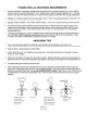
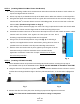
(See Fig. 13 next page, for Cable Routing Diagram) STEP 7: (Installing / Routing EQUALIZER CABLES) Cont. Cable Routing Diagram Fig. 13 5. Repeat above for the second cable. 6. Adjust each equalizer cable to approximately 1/2” side-to-side play. Ensure that each cable has equal tension. Check the carriage height to ensure both carriages are sitting on the same latch.
STEP 8: (Installing / Routing HYDRAULIC HOSES & HYDRAULIC FITTINGS) 1. Install & connect hydraulic hoses & fittings as noted & shown below in (Figs. 14-16) along with the Exploded View #1 diagram on page 21. Note: Ensure Not To Overtighten Hydraulic & Hose Fittings!! a) Remove red cap plug from high pressure port on side of power unit’s valve block. b) Install & secure hydraulic straight fitting (w/ O-ring) to power unit’s high pressure port. (Fig.
STEP 9: (Installing Swing Arms, Floor Plate & Arm Restraints) - Continued 3. Install Arm Restraint mechanisms to each swing arm, as detailed below (Fig. 17). 4. Check for proper engagement for the arm restraints as the gear rack should fully engage the gear on the arm. SAFETY NOTICE! Fig.
STEP 10: (Electrical Connection to POWER UNIT) 1. Have a certified electrician make the electrical connection to the power unit. Use a separate circuit for each power unit, as shown below in (Fig. 18 & 19). Fig. 18 IMPORTANT! The wiring must comply with local code. Protect each circuit with time delay fuse or circuit breaker. For 208V-230V single phase, use 20 amp fuse. WARNING!! Never operate the motor in line voltage less than 208VAC as motor damage may occur.
STEP 11: (Checking Operation) See next page for detailed Operation Instructions: 1. Do not place any vehicle on the lift at this time. Cycle the lift up and down several times to ensure carriage latches click together Safety Latch ‘Cable Pull’ Release and all air is removed from the hydraulic system. 2. To lower the lift, both carriage’s safety latch releases must be manually pulled down to be released to lower lift (Fig.20).
OPERATION INSTRUCTIONS RAISE LIFT 1. Read operating and safety manuals before using lift. 2. Always lift a vehicle according to the manufacturers recommended lifting points 3. Position vehicle between columns, as equally as possible. 4. Adjust swing arms so that the vehicle is positioned with the center of gravity midway between pads. 5. Use truck adapters as needed. Never exceed 9” of pad height. 6.
SAFETY PROCEDURES · Never allow unauthorized persons to operate lift. Thoroughly train new employees in the operation and care of the lift. · Caution: the power unit operates at high pressure. · Remove passengers before raising vehicle. · Prohibit unauthorized persons from being in shop area while lift is in use. · Total lift capacity is 9,000 lbs. with 2,250 lbs. per arm pad. Never exceed the capacity.
WARNING!! OSHA AND ANSI REQUIRE USERS TO INSPECT LIFTING EQUIPMENT AT THE START OF EVERY SHIFT. THESE AND OTHER PERIODIC INSPECTIONS ARE THE RESPONSIBILITY OF THE USER. DAILY PRE-OPERATION CHECK (8 HOURS) The user should perform daily check. Daily check of the safety latch system is very important to prevent expensive property damage, lost production time, serious personal injury and even death.
Only trained maintenance experts should perform lift service for the following items. · Replace hydraulic hoses · Replace chains and rollers. · Replace cables and sheaves. · Replace or rebuild air and hydraulic cylinders as required. · Replace or rebuild pumps / motors as required. · Check hydraulic and air cylinder rod and rod end (threads) for deformation or damage. · Check cylinder mount for looseness and damage. Relocating or changing components may cause problems.
TROUBLE SHOOTING 1. 2. Motor does not run: A. Breaker or fuse blown B. Faulty wiring connections. Call electrician. C. Defective up button. Call electrician for checking. D. Defective Capacitor. Call electrician for checking. Motor runs but will not raise: A. Oil level too low. Oil level should be just under the vent cap port when the lift is down!!! B. Check the clearance in the plunger valve of the lowering handle. C. Remove the check valve cover and clean ball and seat. D.
POWER UNIT PRIMING WARNING!! Failure to properly relieve pressure in the following steps can cause injury to personnel.
EXPLODED VIEW #1 21 TP9KF-TUX Mar 2019
EXPLODED VIEW #2 22 TP9KF-TUX Mar 2019
PARTS LIST ITEM Tux P/N M-Ref P/N DESCRIPTION QTY 1A TP9KF-TUX-001A TPF4-100-00 (A) Mainside Column 2 1B TP9KF-TUX-001B TPF4-100-00 (B) Offside Column 2 2 TP9KF-TUX-002 TPF4-100-10-05 Cable Pulley 6 3 TP9KF-TUX-003 GB894.1-2000 D25 Circlip, D25 4 4 TP9KF-TUX-004 TPF4-100-12 Plastic Cover, Column 2 6 TP9KF-TUX-006 GB5781-86 Bolt 8 7 TP9KF-TUX-007 GB6170-86 Nut 8 8 TP9KF-TUX-008 GB97.
38 TP9KF-TUX-038 PU-2220V-L-H 220V Power Unit 1 39 TP9KF-TUX-039 TT-6934-500-04KY Hyd. Pump Fitting 1 40 TP9KF-TUX-040 D14 O-Ring, Pump Fitting 1 41 TP9KF-TUX-041 TT-6934-500-01NEW Hyd. Hose, Short 1 42 TP9KF-TUX-042 TT-6834-500-01 Hyd. Hex Pipe Fitting 1 43 TP9KF-TUX-043 M14 Combined Washer, M14 4 44 TP9KF-TUX-044 TT-6934-500-06 Throttle Valve 2 44.1 TP9KF-TUX-044.1 TT-6934-500-07 Valve Insert 2 44.2 TP9KF-TUX-044.
LIMITED WARRANTY Structural Warranty: The following parts and structural components carry a five year warranty: Columns Tracks Arms Cross Rails Uprights Top Rail Beam Swivel Pins Legs Carriages Overhead Beam Limited One-Year Warranty: Tuxedo Distributors, LLC offers a limited one-year warranty to the original purchaser of Lifts and Wheel Service equipment in the United States and Canada.